Abstract
To evaluate the interference level of dynamic stray currents from urban rail transit on adjacent buried steel gas pipelines, this paper establishes a two-dimensional resistive network model of subway-soil-pipeline-earth based on bilateral power supply and bidirectional train operation conditions. First, the soil distribution resistance parameters in the track-to-pipeline zone were determined. Second, this model was used to investigate the influence patterns of track resistance, drainage network resistance, train operating position, train interval, and traction substation grounding mode on the pipe-to-ground potential. The model's validity was verified using actual potential monitoring data from gas pipelines adjacent to subway lines. Results indicate that when track resistance increases to 10 times the standard limit (0.01 Ω/km), the maximum positive/negative pipe-to-ground potential deviation rises by approximately 0.4 V. Higher drainage network resistance reduces its ability to collect stray current. When trains pass 500 m and 1500 m away, the maximum positive pipe potential deviation reaches 0.422 V. Different departure intervals for up and down trains cause superposition and cancellation effects in potential waveforms. Interference is minimal during simultaneous departures, peaking at 90 s intervals. Among traction substation grounding configurations, floating grounding causes the least pipeline interference, followed by bilateral direct grounding, with unilateral direct grounding causing the most severe interference. Field measurement data closely aligns with simulation results and consistent trends, validating the model's effectiveness. This study guides the prediction of stray current interference and optimizes the pipeline protection scheme design.
1. Introduction
Subway trains utilize a DC traction power supply system, with the running rails serving as return conductors. Although insulation measures have been implemented between the running rails and the track bed during design, factors such as aging of the system insulation, water accumulation, and construction defects make it difficult to maintain complete insulation between the running rails and the ground during actual operation. As a result, some of the return current leaks into the surrounding soil, forming stray currents
| [1] | Regula M, Siranec M, Otcenasova A, et al. Possibilities of the stray current measurement and corrosive risk evaluation [J]. Electrical Engineering, 2022, 104(4): 497-513.
https://doi.org/10.1007/s00202-021-01408-0 |
[1]
. During the train’s current collection process, the leaked stray current (primary leakage) is first collected by the drainage network installed within the subway tunnel
| [2] | Wu Guangchun, Tan Qiongliang, Li Minfeng, et al. Influence of Metro OVPD on Stray Current Interference on Buried Pipelines [J], Corrosion & Protection, 2022, 43(05): 38-44+8.
https://doi.org/10.11973/fsyfh-202205007 |
| [3] | Xun P, Zhiqiang H, Ben C, et al. On the interference mechanism of stray current generated by DC tram on pipeline corrosion [J]. Engineering Failure Analysis, 2020, 116(10): 47-60 https://doi.org/10.1016/j.engfailanal.2020.104760 |
[2, 3]
. The portion of the current that is not effectively collected further leaks into the ground (secondary leakage), penetrates adjacent buried gas pipelines at points where the anti-corrosion coating is damaged or weak, flows longitudinally along the pipeline, and ultimately exits the pipeline at another point of anti-corrosion coating failure, returning to the negative terminal of the traction substation via the soil. The point where current flows out of the pipeline is located in the electrochemical anode zone, which can trigger localized corrosion and easily lead to safety incidents such as pipeline corrosion perforation
| [4] | ŻAKOWSKI K, DAROWICKI K, ORLIKOWSKI J, et al. Electrolytic corrosion of water pipeline system in the remote distance from stray currents–case study [J]. Case Studies in Construction Materials, 2016, 4: 116-124.
https://doi.org/10.1016/j.cscm.2016.03.002 |
| [5] | MO S, YANG S, LU X, et al. Investigation of dynamic stray current interference from direct current system with city pipelines [M]. ICPTT 2013: Trenchless Technology. 2013: 883-90.
https://doi.org/10.1061/9780784413142.093 |
| [6] | Zhao Cheng, Fan Liepeng. Analysis of Impact of Subway Stray Current on Buried Steel Gas Pipelines [J]. Gas & Heat, 2025, 45(11): 67-70.
https://doi.org/10.13608/j.cnki.1000-4416.2025.11.002 |
| [7] | HE San. YU Rui. ZHANG Jianxiong. et al. Corrosion Characteristics of X70 Steel Under AC-DC Mixed Interference [J]. Journal of Southwest Petroleum University, 2013: 883-90.
https://doi.org/10.11885/j.issn.1674-5086.2023.07.31.01 |
[4-7]
. Although the extent of stray current interference can be assessed through potential measurements along the track, the operating position of subway trains and the magnitude of traction current exhibit significant time-varying and random characteristics
| [8] | CHARALAMBOUS C A. Comprehensive modeling to allow informed calculation of DC traction systems’ stray current levels [J]. IEEE Transactions on Vehicular Technology, 2017, 66(11): 9667-77.
https://doi.org/10.1109/TVT.2017.2748988 |
[8]
. Consequently, stray currents display strong dynamic fluctuations
, causing the pipeline potential to rapidly switch between cathodic and anodic regions
| [10] | ZAKOWSKI K, DAROWICKI K. Methods of evaluation of the corrosion hazard caused by stray currents to metal structures containing aggressive media [J]. Polish Journal of Environmental Studies, 2000, 9(4): 237-42. |
| [11] | KERIMOV A, SPIRIN P, KERIMOV R. Relationship between the parameters of stray current circuits and the traction load [J]. Protection of metals, 2006, 42(4).
https://doi.org/10.1134/S0033173206040187 |
[10, 11]
. However, no clear conclusions have yet been reached regarding how the operational status of the subway and the electrical parameters of the traction system affect the potential distribution of adjacent pipelines.
To date, a significant number of scholars have conducted in-depth studies on the distribution characteristics of stray currents in subway systems. McCollum
| [12] | MCCOLLUM B, LOGAN K H. Leakage of currents from electric railways [M]. US Government Printing Office, 1916. |
[12]
was the first to introduce the concept of stray current leakage rate by establishing a two-layer resistive network model comprising the “rail-to-ground” path. As the model continued to evolve, Zaboli
| [13] | ZABOLI A, VAHIDI B, YOUSEFI S, et al. Evaluation and control of stray current in DC-electrified railway systems [J]. IEEE Transactions on Vehicular Technology, 2016, 66(2): 974-80. https://doi.org/10.1109/TVT.2016.2555485 |
[13]
used MATLAB to develop a stray current distribution model for trains and conducted a comparative analysis of stray current distribution patterns under different soil conditions, both with and without a drainage grid. Liu
| [14] | LIU M, LIN S, ZHAO L, et al. Study on dynamic characteristics of metro stray current based on CDEGS; proceedings of the International Conference on Electrical and Information Technologies for Rail Transportation, F, 2017 [C]. Springer.
https://doi.org/10.1155/2022/6845847 |
[14]
developed a stray current simulation model based on CDEGS. Through an analysis of speed-limited operation modes, they proposed a control strategy based on cumulative leakage charge calculations to prevent buried conductors from exceeding voltage thresholds and suffering corrosion. Ibrahem
| [15] | IBRAHEM A, ELRAYYAH A, SOZER Y, et al. DC railway system emulator for stray current and touch voltage prediction [J]. IEEE Transactions on Industry Applications, 2016, 53(1): 439-46. https://doi.org/10.1109/TIA.2016.2606367 |
[15]
designed a railway DC stray current simulation system capable of investigating the effects of stray currents and contact voltages, as well as evaluating mitigation measures prior to practical engineering applications. Yang
established a stray current distribution model that accounts for parameter inhomogeneity, analyzing the distribution characteristics of rail-to-ground voltage and surface potential gradients. Song
| [17] | SONG C, LI Z, WANG H, et al. Analysis of influence law of rail transition resistance on subway stray current; proceedings of the 2022 7th Asia Conference on Power and Electrical Engineering (ACPEE), F, 2022 [C]. IEEE.
https://doi.org/10.1109/ACPEE53904.2022.9783950 |
[17]
used the Malz module of the CDEGS software to construct soil and conductor structure models and investigated the distribution patterns of stray currents in subway systems under different track-to-ground transition resistances. Wang
| [18] | WANG C, LI W, WANG Y, et al. Evaluation model for the scope of DC interference generated by stray currents in light rail systems [J]. Energies, 2019, 12(4): 746.
https://doi.org/10.3390/en12040746 |
[18]
established a model of the surface potential gradient of soil caused by stray current leakage under point-source excitation and analyzed the effect of variations in track-to-ground transition resistance on the potential gradient. When performing numerical solutions using a discretized resistive network model, the selection of resistance parameters and the definition of boundary conditions can significantly affect the computational results. To address this, Chen
modeled the vertical soil resistance and simulated points of corrosion layer damage by setting pipe-soil transition resistances, thereby investigating their impact on stray current distribution; however, this model assumes that all leakage current flows into the pipe, which differs somewhat from actual conditions. Szymenderski
| [20] | SZYMENDERSKI J, MACHCZYŃSKI W, BUDNIK K. Modeling effects of stochastic stray currents from DC traction on corrosion hazard of buried pipelines [J]. Energies, 2019, 12(23): 4570. https://doi.org/10.3390/en12234570 |
[20]
established distributed and centralized dynamic current transfer models based on ground loop theory. By calculating the polarization effects of underground metal facilities, they investigated the dynamic distribution of stray currents. The results indicate that this model can effectively predict the extent of stray current interference on underground metal pipelines near DC rail transit systems. However, most of the aforementioned studies have focused on the distribution patterns of stray currents in the rail-to-ground system, and the models developed generally do not fully account for the influence of adjacent buried metal pipelines and their protective coating systems. At the same time, existing evaluation methods typically rely on surface potential gradients to determine stray current intensity and the need for protection
, failing to systematically reflect the direct impact of dynamic stray currents on pipeline potential distribution; consequently, these methods remain limited in assessing the actual degree of interference experienced by buried pipelines.
This paper establishes a two-dimensional dynamic resistance network model of the rail track-soil-pipeline-ground system suitable for bidirectional train operations under a dual-power-supply mode. It determines a method for calculating the distributed soil resistance in the area between the track and the pipeline, and analyzes the influence of key parameters, such as track resistance, drainage network resistance, and train location. Additionally, by comparing the stray current leakage characteristics and differences in the pipe-to-soil potential distribution under various traction substation grounding configurations (floating, single-side direct, and double-side direct grounding), this study provides a basis for interference mitigation and pipeline protection design.
2. Model Establishment
2.1. Two-Dimensional Equivalent Resistance Network Model
The subway traction power supply system primarily consists of traction substations, overhead contact lines, pantographs, subway trains, running rails, and drainage grids. The positive terminal of the traction substation is connected to the overhead contact line via feeder lines; subway trains draw current from the overhead contact line through pantographs, and the current returns to the negative terminal of the traction substation via the running rails
| [23] | LI Xuefei, SUN Wenbin, DAI Jun, et al. Research on the grounding system of dual-system trains [J]. Urban rapid rail transit, 2025, 38(3): 131-137.
https://doi.org/10.3969/j.issn.1672-6073.2025.03.018 |
| [24] | Liu Jianhua, Cheng Songjin. Improvement of Frame Current Protection Design of Subway Traction Substation [J]. Mechanical & Electrical Engineering Technology, 2025, 44(10): 16-22. |
[23, 24]
. Due to the presence of track-to-ground contact resistance, a portion of the current leaks into the soil and infiltrates adjacent buried metal pipelines.
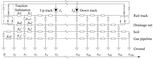
This model consists of a two-dimensional equivalent circuit formed by longitudinal and transverse resistances, covering the narrow strip of soil beneath the railway and adjacent buried metal pipeline structures, as shown in
Figure 1. The model is 2,000 m long, with a longitudinal element length
x = 20 m; trains are powered jointly by the two traction substations. Here,
Iu is the traction current of the train on the up line (A),
Id is the traction current of the train on the down line (A),
Rr is the longitudinal resistance of the track (Ω),
Rrm is the transition resistance from the track to the drainage grid (Ω),
Rm is the longitudinal resistance of the drainage grid (Ω),
Rh is the vertical resistance of the soil (Ω),
Rl is the longitudinal resistance of the soil (Ω),
Rf is the resistance of the pipeline’s anti-corrosion coating (Ω), and
Rp is pipeline longitudinal resistance (Ω). The currents at each node satisfy Kirchhoff’s current law.
Figure 1. Model of Bidirectional Trains in Dual-Power Supply Mode.
2.2. Soil Resistance
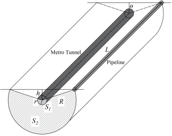
Soil resistance is decomposed into vertical resistance and longitudinal resistance along the pipeline. Since the distance between the pipeline and the track is much greater than the pipe diameter, the pipeline cross-section can be simplified to a point-like current collector, and the influence of its radial geometric dimensions on the current field distribution can be neglected. Assuming that stray currents leak uniformly along the circumference of the tunnel surface and gradually form an approximately uniform horizontal distribution as they diffuse toward the ground insulation boundary, the vertical flow region of the stray currents is modeled as a fan-shaped shadow region, as shown in
Figure 2.
Figure 2. Soil Resistivity Calculation Cross-Section.
Let I be the tunnel leakage current. Then, the current density J at a distance r from the center of the tunnel is:
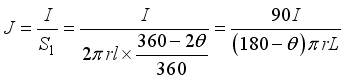 (1)
(1) Where: L is the distance between traction substations (m); r is the tunnel radius (m); θ is the angle between the line connecting the pipe and the rail and the perpendicular line from the center of the tunnel to the ground (°).
Based on the differential form of Ohm’s law, E = ρJ, the radial electric field intensity Er established in the soil by the stray current source can be determined. Taking the center of the tunnel as the potential reference point and integrating along the radial path between the pipeline and the tunnel yields the soil potential difference Ur between the two; from this, the soil vertical resistance Rh is derived as follows:
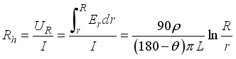 (2)
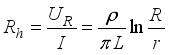
(2) When the distance between the track and the pipeline is much greater than the depth of the subway tunnel (
R >> h),
θ≈ 90°, the electrode can be approximated as a semicylinder, and Eq. (
2) simplifies to:
 (3)
(3) The formula for calculating the soil vertical resistance, RL, is as follows:
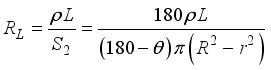 (4)
(4) In the equation: ρ is the soil resistivity (Ω·m); L is the distance between traction substations (m); r is the tunnel radius (m); R is the distance between the track and the tunnel wall (m); h is the tunnel depth (m).
2.3. Pipeline Coating Resistance
To prevent underground pipelines from corrosion caused by soil and atmospheric conditions, the outer walls of high-pressure gas pipelines are typically coated with reinforced polyethylene (3PE coating), which offers excellent insulation properties. Since the longitudinal electrical resistance of the anti-corrosion coating is much higher than that of the pipeline itself, it can be assumed that the coating provides complete insulation along the pipeline’s longitudinal axis, allowing only radial electrical resistance to be considered. Although the volume resistivity of polyethylene can reach the order of 1013 Ω·m, under actual installation and operating conditions, the actual insulation performance of the anti-corrosion coating is significantly reduced due to factors such as the penetration of soil electrolytes, microscopic defects in the coating, and moisture at the interface. This paper uses surface resistivity, which is convenient for field test measurement and evaluation, to calculate the resistance Rf of the anti-corrosion coating per unit length of pipe. The expression is as follows:
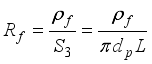 (5)
(5) Where: dp is the outer diameter of the pipe (m); ρf is the resistivity of the pipe's anti-corrosion surface (Ω·m2); and S3 is the cross-sectional area of the anti-corrosion coating (m2).
2.4. Pipeline Longitudinal Resistance
The cross-sectional shape of a metal pipe is a circle. Since the pipe diameter is much greater than the wall thickness, the formula for calculating the longitudinal resistance of the pipe is as follows:
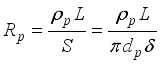 (6)
(6) Where: is the pipe wall thickness (m); ρp is the resistivity of the pipe steel (Ω·m); sand S is the cross-sectional area of the pipe (m2).
3. Model Validation
3.1. Field Test
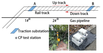
The AB section of a subway line in one city (with a distance of approximately 2,000 m between traction substations) was selected. As shown in
Figure 3, an underground high-pressure gas pipeline runs parallel to the subway line at a horizontal distance of approximately 200 m. To monitor interference from dynamic stray currents, stray current monitoring systems were installed at CP test stations 1 and 2 along the pipeline. Corrosion test coupons and saturated copper sulfate reference electrodes were buried simultaneously, and continuous pipe-to-soil potential data were collected for 24 hours at 1 s intervals.
Figure 3. Field Testing Diagram.
3.2. Model Verification
The values of the model’s key parameters are shown in
Table 1. These parameters were selected primarily based on field measurement data, engineering design documentation, and relevant technical standards.
Table 1. Model parameter values.
Parameters | Definitions | Values |
L | Distance between traction substations | 2000 m |
| Vertical unit length | 20 m |
h | Tunnel depth | 18 m |
r | Tunnel radius | 3 m |
Dpg | Horizontal distance between pipes and rails | 200 m |
hp | Pipe burial depth | 1.5 m |
dp | Pipe diameter | 300 mm |
| Pipe wall thickness | 5 mm |
| Soil resistivity | 50 |
Rr | Track longitudinal resistance | 0.22 |
Rn | Longitudinal resistance of the drainage grid | 2 |
Rrm | Transition resistance between the rail and the flow grid | 1 |
Ut | Traction voltage | 1600 V |
Iu, Id | Train traction current | Flow-rate curve |
| Pipe resistivity | 1.3×10⁻⁷ |
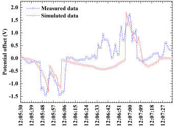
Figure 4. Comparison of Measured and Simulated Pipe-to-Soil Potential Offset.
Figure 4 compares the measured data with the simulation results for the pipe-to-soil potential offset at Test point 2 (corresponding to a location approximately 1,000 m from Traction Substation A) during a single train operation cycle. The measured pipe-to-soil potential offset ranged from -1.40 V to +1.76 V, while the model calculations ranged from -1.31 V to +1.79 V. The measured values show a high degree of consistency with the simulated potential fluctuation trends, accurately characterizing the pipe-to-soil potential response under typical operating conditions such as train startup, acceleration, and coasting. Throughout the entire period, the relative peak error between the two was less than 10%. The primary causes of the deviation stemmed from the homogenization treatment of the soil medium and the failure to account for the shunting effect of unknown underground metal structures. Overall, the model effectively reproduces the potential fluctuation characteristics and variation patterns of the pipeline under dynamic stray current interference, thereby validating its applicability in stray current interference assessment.
4. Analysis of Factors Affecting the Degree of Pipeline Interference
4.1. Impact of Longitudinal Resistance of Railway Track
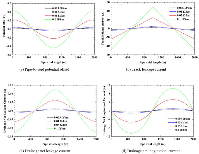
To investigate the effect of track longitudinal resistance on stray current interference characteristics, simulation calculations were performed using values of 0.005, 0.01, 0.05, 0.1, and 0.5 Ω/km.
The results in
Figure 5(a) show a significant positive correlation between track longitudinal resistance and the maximum amplitude of the pipe-to-soil potential offset; that is, the higher the track longitudinal resistance, the more pronounced the increase in the maximum amplitude. When the track longitudinal resistance was increased from the standard limit of 0.01 Ω/km to 0.1 Ω/km, the increase in the maximum positive and negative potential offset was approximately 0.4 V.
Figures 5(b) to (d) further reveal the underlying mechanism: an increase in track longitudinal resistance causes a rise in the longitudinal voltage drop across the rails, prompting more traction current to leak into the soil. Although the current collection capacity of the drainage network increases accordingly, its collection efficiency is limited. Consequently, uncaptured current diffuses into the soil environment as secondary leakage, causing a corresponding increase in stray current density in the soil, which ultimately leads to a significant intensification of stray current interference affecting buried pipelines.
Figure 5. Simulation Results Under Different Track Longitudinal Resistance.
4.2. Effect of Longitudinal Resistance of Drainage Net
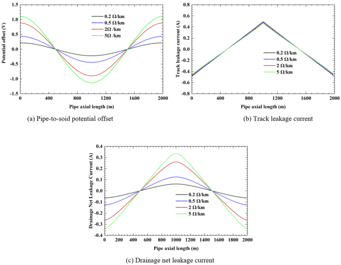
Assuming a track longitudinal resistance of 0.05 Ω/km, simulation tests were conducted using drain network longitudinal resistances of 0.2, 0.5, 2, and 5 Ω/km.
The results are shown in
Figure 6. An increase in the drain network’s longitudinal resistance leads to a significant increase in the amplitude of the pipe-to-soil potential offset. Changes in the longitudinal resistance of the drainage network have no significant effect on the total amount of stray current leaking into the soil along the return track. The higher the longitudinal resistance of the drainage network, the more significant its own longitudinal voltage drop becomes. This results in an uneven ground potential distribution along the drainage network, which in turn increases current leakage from the drainage network and ultimately leads to an increase in the total amount of stray current entering the buried pipeline.
Figure 6. Simulation Results for Different Longitudinal Resistances of Drainage Net.
4.3. Effect of Train Running Position
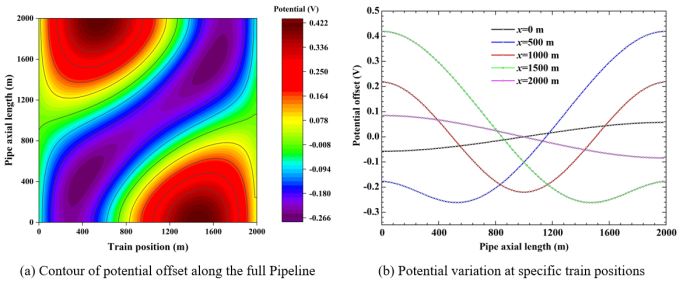
To investigate the spatial distribution characteristics of stray current interference from a single-unit train on pipelines, the train was set to draw a constant current of 2000 A while traveling at a constant speed through the AB traction section. The study analyzed the impact of the train’s position on the potential shift along the entire pipeline. The results in
Figure 7 indicate that in the first half of the AB traction section, the pipeline segment directly beneath the train exhibits a negative potential shift, with stray current flowing into the pipeline; this area is the cathodic zone. In contrast, pipeline segments farther from the train exhibit a positive potential shift, with stray current flowing out of the pipeline; this area is the anodic zone. When the train travels through the 0-500 m section, the peak positive potential shift of the pipe-to-soil potential across the entire pipeline tends to increase; when the train reaches the 500 m and 1500 m points, the amplitude of the positive potential shift between the pipeline and ground across the entire pipeline reaches a maximum of 0.422 V; when the train travels through the 500-1000 m section, the amplitude of the positive potential shift between the pipeline and ground shows a decreasing trend.
Figure 7. Effect of Train Position on Pipeline Potential Offset.
It is worth noting that when the train is located at
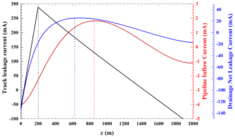
x = 200 m, the peak track leakage current occurs at the train’s position, as shown in
Figure 8, while the peak leakage current in the drainage network lags slightly behind the train’s position (exhibiting a right-shifted characteristic); conversely, the peak stray current entering the pipeline is closer to the midpoint of the power supply section. This reveals that during the propagation of dynamic stray current interference from the source (the track) to the distant pipeline, there is a propagation pattern characterized by spatial attenuation of intensity and a lag in the peak.
Figure 8. Current distribution in the track, drainage grid, and inflow pipeline when the train is located at x=200m.
4.4. Effect of Departure Interval of Up and Down Trains
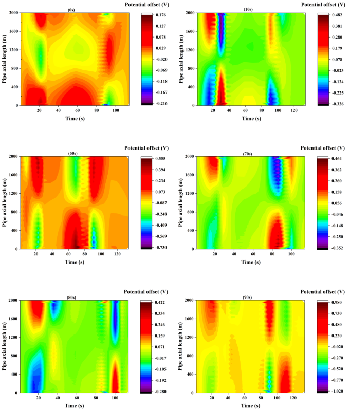
The stray currents generated by the traction and regenerative braking of up and down trains are strong and flow in opposite directions. Differences in train departure intervals can cause the stray current fields generated by the two trains to exhibit varying degrees of superposition or cancellation effects in the soil medium and pipelines. This paper selects six typical departure intervals, including simultaneous departure, 10 s intervals (with slight temporal overlap between current collection and return for the two trains), 50 s intervals (no temporal correlation between current draw and return for the two trains), 70 s intervals (the peak current draw of the upstream train synchronizes with the peak regenerative braking of the downstream train), 80 s intervals (the current draw of the upstream train and the return current of the downstream train are numerically balanced), and 90 s intervals (the startup current draw of the upstream train synchronizes with the startup return current of the downstream train). Using a single operating cycle of the up and down trains as a reference, time response curves of the ground potential offset at the measurement point were plotted for different departure intervals.
The results are shown in
Figure 9, where the up and down trains depart simultaneously, their stray current fields partially cancel each other out, resulting in relatively small fluctuations in pipeline potential. As the departure interval changes, phase differences arise between the interference waveforms of the two trains, leading to complex superposition effects. When trains depart simultaneously, the maximum positive deviation of the measured point’s pipe-to-ground potential is 0.176 V, and the maximum negative deviation is -0.216 V, with peaks occurring around 20 s and 90 s; when the downbound train departs with a 90 s interval, the maximum positive deviation is 0.98 V, and the maximum negative deviation is -1.02 V. It can be seen that the pipeline experiences the least interference when trains depart simultaneously, while the peak stray current interference increases significantly when the departure interval is 90 s. This indicates that optimizing the train schedule to avoid strong interference between up and down trains can serve as a supplementary measure to mitigate stray current interference.
Figure 9. Variation in pipe-to-soil potential shift when up and down trains at different departure intervals.
4.5. Effect of Traction Substation Grounding Mode
The grounding method of a DC traction substation directly affects the path and magnitude of stray current leakage to ground, making it a critical aspect of system design
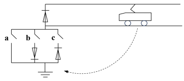
. The main grounding methods include: Direct grounding: This involves establishing a direct electrical connection between the DC negative busbar and the grounding grid. It helps control rail potential and ensure safety, but provides a low-resistance leakage path for stray currents. Floating grounding: The DC negative busbar has no electrical connection to ground, resulting in high rail-to-ground insulation. This significantly suppresses stray current leakage but may cause an increase in rail potential, necessitating the installation of a rail potential limiting device; Bilateral direct grounding.
To investigate the effects of grounding methods, an equivalent circuit shown in
Figure 10 was established for simulation. Three typical configurations were simulated using different switch combinations: floating grounding (switches a, b, and c all open), single-side direct grounding (switch a closed, switches b and c open), and double-side direct grounding. Considering that multiple different grounding methods may coexist in actual sections, this paper compares the three typical scenarios described above.
Figure 10. Schematic of Grounding Methods for Traction Substations.
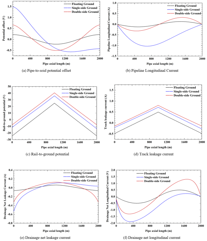
The results are shown in
Figure 11. A comparison of the pipeline potential offset reveals that when the traction substation is grounded via a floating grounding system, the potential offset between the pipeline and ground is minimal; this is followed by a system with direct grounding on both sides. In contrast, when the substation is grounded on one side only, the pipeline potential offset is greatest, and the interference is most severe. Analysis of the current distribution (
Figures 11c-f) reveals the cause: when the substation is directly grounded, it provides a low-resistance “shortcut” for the traction current, resulting in a significant increase in the total amount of primary stray current leaking from the rails to ground, with bilateral grounding causing slightly higher levels than unilateral grounding. Although the current collected by the drainage network also increases accordingly, the secondary leakage current also increases significantly, ultimately resulting in the largest net increase in stray current entering the pipeline. Therefore, provided safety standards are met, prioritizing floating grounding can effectively reduce the corrosion risk posed by stray currents to external buried pipelines at the source.
Figure 11. Simulation Results for Different Grounding Modes of Traction Substations.
5. Conclusions
This paper proposes a method for calculating the distributed soil resistance in track-pipeline areas and clarifies the regulatory mechanisms of track longitudinal resistance and drainage network longitudinal resistance on stray current interference. These resistance parameters significantly influence pipeline potential shifts; when track resistance increases to 10 times the standard limit, interference intensifies significantly, while an increase in drainage network resistance reduces current collection efficiency and exacerbates the degree of pipeline interference.
Train operations cause a differential distribution of anodes and cathodes along pipelines and result in a lag effect in interference peaks. By regulating the coupling effects of stray current fields through train headway adjustments, the intensity of pipeline interference can be modified; optimizing train schedules is a feasible approach for mitigating pipeline interference.
The grounding configuration of traction substations significantly affects pipeline interference. With floating grounding, the fluctuation range of the pipe-to-soil potential shift is smallest for adjacent pipelines, resulting in minimal interference; bilateral direct grounding is the next best option; and unilateral direct grounding causes the most severe stray current interference. During the design and retrofitting of subway traction substations, grounding methods that limit stray current leakage should be prioritized to provide source-level protection for adjacent buried metal pipelines.




 Share This Article
 Twitter
 Linked In
 Facebook
 Copy
Copy Download