This report constitutes of, as the title for this paper, Analysis of S-band Parabolic Antenna Performance for Microsatellite Communication Systems. The objective of the paper is to build an intelligent antenna in order to receive with less noise signal transmitted by Microsatellite. It will be a challenging project since the distance of satellite from antenna is quite far with a lot of noise can affect the transmission process. Microsatellite missions enable innovative scientific experiments using a low-cost platform but are limited by their small size and available solar power. This imposes strict power budgets on radio links. Enhancing ground station antenna systems can improve communication margins by increasing forward gain, forward-to-backward ratio, and directivity, ultimately boosting link performance with the satellite. The purpose of this paper was to analyze the performance evaluation of parabolic reflector with horn feed antenna for communication with frequency operating between 2 GHz and 3 GHz Amateur S-band. Parabolic antennas serve as effective high-gain solutions for microsatellite communication. The far-field radiation pattern produced by a parabolic reflector is influenced by the feed element's radiation pattern and the specific type and dimensions of the reflector employed. In this study, the antenna system is designed and simulated in the CST Microwave Studio to achieve specific requirements which are minimum power reflected back to the source and maximum gain with minimum front-to-back ratio, VSWR and radiation pattern for the antenna system.
This is an Open Access article, distributed under the terms of the Creative Commons Attribution 4.0 International License (http://creativecommons.org/licenses/by/4.0/), which permits unrestricted use, distribution and reproduction in any medium or format, provided the original work is properly cited.
Parabolic reflector antennas are widely utilized in communication systems, radar and radio astronomy due to their high gain, directivity and ability to focus electromagnetic waves effectively. This antenna was first developed and used in the early 20th century with significant contributions from pioneers in the fields of radio and radar
[2]
P.-Skiddaw. A small dipole-fed resonant reflector antenna with high efficiency, low cross polarization, and low sidelobes. IEEE Trans. Antennas Propagate., vol. AP-33, no. 12.
[3]
Reichlin. Foundations for Microwave Engineering. 2nd ed., IEEE Press, 2001.
[2, 3]
. The fundamental principle behind a parabolic reflector is its geometric shape which ensures thar all incoming parallel rays reflect and converge at the focal point. Conversely, when a source such as a feed horn is placed at the focal point, the reflected waves become collimated into a highly directional beam
[5]
Antenna Theory, Analysis and Design, Third Edition by Constantine A. Balanis. Copyright 2005 by John Wiley & Sons, Inc.
[7]
Anthony Shelley. A 24FT/7. 3M PARABOLIC REFLECTOR ANTENNA PERFORMANCE & FEED DESIGN ANALYSIS. the Faculty of the College of Science & Technology Morehead State University, Master. Thesis, 2010.
[5, 7]
. The feed horn, typically a waveguide structure is used to illuminate the parabolic reflector uniformly and efficiently. This combination enables excellent performance in terms of gain and sidelobe suppression. The positioning and design of the feed horn are crucial as they significantly affect the overall radiation pattern and efficiency of the antenna system
[4]
Anindya Kumar Kundu, MD. Tofel Hossain Khan, Wahida Sharmin, Md. Osman Goni. Design and Performance Analysis of a Dual Band Parabolic Reflector Antenna with Waveguide Dipole Feed. Proceedings of 2013 2nd International Conference on Advances in Electrical Engineering (ICAEE 2013) 19-21 December, 2013, Dhaka, Bangladesh.
[6]
A. Heldring. Full wave analysis of electrically large reflector antennas. Ph.D. Dissertation, Delft Univ, Press, The Netherlands, April 2002.
[4, 6]
.
The design of the parabolic antenna for microsatellite applications involving addressing unique constraint such as limited onboard power, space and weight as well as the need for resilience against the harsh condition of space.
The parabolic antenna offers the highest gain typically exceeding 30 dB focusing signals into a narrow beam. This statement describes a key feature of parabolic antennas commonly used in satellite communications due to their high efficiency and directivity. Gain represents the antenna’s effectiveness in focusing radio frequency signals toward a designated direction
[10]
Hagstrom, T., Stavoli, R., Wang, A., & Axford, R. Performance--The Effects of Paint on Large Aperture Ka-Band Antennas. In 2014 IEEE Military Communications Conference (pp. 1338-1343). IEEE.
[11]
Maral, G., Bousquet, M., & Sun, Z. Satellite communications systems: systems, techniques and technology. John Wiley & Sons. (2020).
[10, 11]
.
A high-gain antenna can focus more power in the desired direction (or receive more energy from a specific direction) compared to other types of antennas. A gain of 30 dB means the antenna amplifies the power by 1000 times compared to an isotropic antenna (a theoretical antenna that radiates equally in all directions)
[1]
Fahad Shamshad. Simulation Comparison between HFSS, CST and WIPL-D for Design of Dipole, Horn and Parabolic Reflector Antenna. Advances in Computational Mathematics and its Applications (ACMA) Vol. 1, No. 4, 2012, ISSN 2167-6356.
[1]
.
The narrow beam means the antenna focuses the signal into a tight area rather than spreading it widely. This feature reduces interference from other signals and improves the clarity and reliability of the communication link. Ideal for long-distance communication like satellite-to-ground or inter-satellite links where signal strength needs to be maintained over vast distances
[8]
Chaurasiya, K. and Kumar, S., Design and analysis of parabolic reflector using Matlab. Int. J. of Advanced Research in Electrical, Electronics and Instrumentation Engineering, 4(3), (2015).
[9]
Nafati A. Aboserwal, Constantine A. Balanis, Life Fellow, IEEE, and Craig R. Birtcher, “Conical Horn: Gain and Amplitude Patterns”, IEEE Transactions on antennas and propagation, vol. 61, no. 7, July 2013.
[8, 9]
. Highly directional enabling precise targeting of communication. So, the parabolic antenna’s ability to concentrate energy into a narrow beam makes it the go-to choice for high-performance communication systems requiring long-range and high-gain characteristics
[12]
Basari, “Development of Simple Antenna System for Land Mobile Satellite Communications,” Doctoral Dissertation, February, 2011.
[13]
CST Microwave Studio by CST STUDIO SUIT STUDENT Version 2017.
[12, 13]
.
In this study investigates the fundamental principles of parabolic antenna design its adaptation for microsatellite platforms and the challenges associated with optimizing performance within the constraints of miniaturized satellite architectures. A focus is placed on key design parameters including reflector size, feed alignment, beam width and frequency selection with an emphasis on enhancing communication reliability and signal clarity in orbital environments.
2. Antenna Design
The antenna design could be developed based on the following steps and analyses.
2.1. Mathematical Analysis
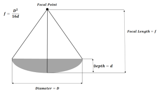
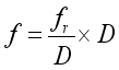
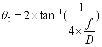
The design of the proposed antenna is shown in Figure 1. The design of the proposed parabolic antenna with focal point was modeled the classical equations.
Figure 1. Mathematical Diagram of Parabolic Reflector.
Focal length,
(1)
Radius of dish,
(2)
Depth of dish,
(3)
Angle from center to edge of dish,
(4)
Beamwidth,
(5)
Wavelength of frequency,
(6)
(speed of light)
=operating frequency
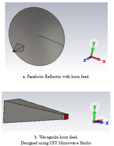
2.2. Proposed Antenna Architecture
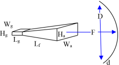
Figure 2 shows the structure dimensions of a proposed S band parabolic reflector antenna with horn feed. All of the specific dimension of the parabolic reflector antenna with horn feed was shown in Table 1. The parabolic antenna resembles with the diameter of 2.8 m and horn antenna for s band selected WR284 Rectangular Waveguide Sizes from International Electrotechnical Commission (IEC). The proposed antenna structure comprises a parabolic reflector and horn feed strategically placed at its focal point to achieve high directivity and gain. The design leverages the reflective properties of a parabolic surface which transforms spherical waveforms resulting in a highly collimated beam. The horn feed illuminates the reflector with a radiation pattern designed to minimize spillover, ensure uniform illumination of the aperture and reduce side lobes and back lobes.
Figure 2. Geometry and Dimensions of Parabolic antenna.
Table 1. Design Parameter Specifications of Parabolic Reflector with horn feed.
Reflector (mm)
Horn (mm), WR284 for S-band
D = 2800 (2.8 m)
Lf = 700
F = 2197
Lg = 30
d = 223
Wg = 97.7
Hg = 59.5
Wa = 352.8
Ha = 261.7
2.3. Rectangular Horn Feeder
Rectangular horn feeder is particularly advantages for microsatellite applications with ground stations due to their combination of compact design, efficient waveguide coupling and compatibility with parabolic reflector.
Rectangular horn acts as gradual transitions from rectangular waveguide modes (typically TE10) to free-space electromagnetic waves. This minimizes reflections and achieves low voltages standing wave radio (VSWR) typically below 2: 1.
The rectangular horn’s combination of wide bandwidth (10:1 ratio), stable radiation patterns and efficient waveguide matching makes it particularly suitable for feed applications in directive antenna systems. Recent study shows optimized performance in 2.1 GHz band using multimode excitation achieving beamwidth consistency within 0.4° variation. Combined with a parabolic dish, the system achieves 30-40 dB total gain critical for overcoming free-space path loss in satellite-ground link. Rectangular horn provides low sidelobes (-20 dB typical) reducing interference in crowed frequency band. The gradual flare shape minimizes reflections and insertion losses ensuring efficient power transfer between the waveguide and free space.
Waveguide aperture is designed based on WR-284 rectangular waveguide standard, this standard is giving length of horn 730 mm and width and high of waveguide is 97.7 mm and 59.5 mm. The high and width of front-flap of horn is 216.7 mm and 352.8 mm.
Table 2. Proposed Parabolic Reflector Antenna Parameters and Values.
DesignedParabolicReflectorAntennaParameters
SimulationResults
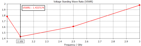
VSWR
1.4
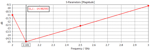
Returnloss(indB)
-14.98 dB
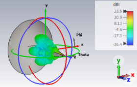
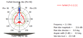
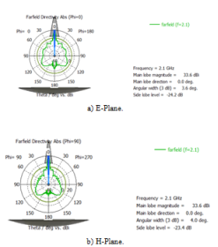
Gain(indB)
33.6 dB
Directivity(indB)
33.58 dB
AntennaEfficiency(%)
78.46%
Beamwidth(deg)
4°
Sidelobegain(indB)
-23.4 dB
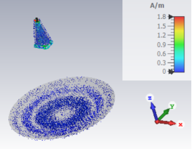
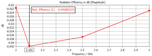
RadiationEfficiency(indB)
-0.041 dB
4. Conclusions
The purposed antenna operates within the 2.1 GHz frequency band and is designed to investigate the radiation characteristics of a parabolic reflector using CST Studio Suite. The system employs a rectangular horn feed integrated with a WR-284 waveguide. At the resonant frequency of 2.1 GHz, the antenna performance was evaluated and validated through simulations in CST Microwave Studio. The observed results include a return loss of -14.98 dB, a VSWR of 1.4, directivity of 33.58 dB and a gain of 33.6 dB recorded under conditions where |S1,1| < -10 dB and VSWR < 2. The simulated total efficiency reached 82.9% with a 3 dB beamwidth of approximately 4°. These results comprehensively demonstrate the high-performance capability of the proposed reflector antenna design.
In this paper, the simulation results validate the feasibility of the parabolic antenna for micro satellite communication, achieving peak values that highlighting their ability to provide high-gain, focused transmissions with minimal power consumption.
Acknowledgments
The authors are deeply indebted to many colleagues whose insights and support were instrumental in Space Systems Engineering Department of Myanmar Aerospace Engineering University.
Conflicts of Interest
The authors declare no conflicts of interest.
References
[1]
Fahad Shamshad. Simulation Comparison between HFSS, CST and WIPL-D for Design of Dipole, Horn and Parabolic Reflector Antenna. Advances in Computational Mathematics and its Applications (ACMA) Vol. 1, No. 4, 2012, ISSN 2167-6356.
[2]
P.-Skiddaw. A small dipole-fed resonant reflector antenna with high efficiency, low cross polarization, and low sidelobes. IEEE Trans. Antennas Propagate., vol. AP-33, no. 12.
[3]
Reichlin. Foundations for Microwave Engineering. 2nd ed., IEEE Press, 2001.
[4]
Anindya Kumar Kundu, MD. Tofel Hossain Khan, Wahida Sharmin, Md. Osman Goni. Design and Performance Analysis of a Dual Band Parabolic Reflector Antenna with Waveguide Dipole Feed. Proceedings of 2013 2nd International Conference on Advances in Electrical Engineering (ICAEE 2013) 19-21 December, 2013, Dhaka, Bangladesh.
[5]
Antenna Theory, Analysis and Design, Third Edition by Constantine A. Balanis. Copyright 2005 by John Wiley & Sons, Inc.
[6]
A. Heldring. Full wave analysis of electrically large reflector antennas. Ph.D. Dissertation, Delft Univ, Press, The Netherlands, April 2002.
[7]
Anthony Shelley. A 24FT/7. 3M PARABOLIC REFLECTOR ANTENNA PERFORMANCE & FEED DESIGN ANALYSIS. the Faculty of the College of Science & Technology Morehead State University, Master. Thesis, 2010.
[8]
Chaurasiya, K. and Kumar, S., Design and analysis of parabolic reflector using Matlab. Int. J. of Advanced Research in Electrical, Electronics and Instrumentation Engineering, 4(3), (2015).
[9]
Nafati A. Aboserwal, Constantine A. Balanis, Life Fellow, IEEE, and Craig R. Birtcher, “Conical Horn: Gain and Amplitude Patterns”, IEEE Transactions on antennas and propagation, vol. 61, no. 7, July 2013.
[10]
Hagstrom, T., Stavoli, R., Wang, A., & Axford, R. Performance--The Effects of Paint on Large Aperture Ka-Band Antennas. In 2014 IEEE Military Communications Conference (pp. 1338-1343). IEEE.
[11]
Maral, G., Bousquet, M., & Sun, Z. Satellite communications systems: systems, techniques and technology. John Wiley & Sons. (2020).
[12]
Basari, “Development of Simple Antenna System for Land Mobile Satellite Communications,” Doctoral Dissertation, February, 2011.
[13]
CST Microwave Studio by CST STUDIO SUIT STUDENT Version 2017.
Lwin, T. O., Wynn, A. K. (2025). Analysis of S-band Parabolic Antenna Performance for Microsatellite Communication Systems. American Journal of Electromagnetics and Applications, 13(1), 8-14. https://doi.org/10.11648/j.ajea.20251301.12
Lwin, T. O.; Wynn, A. K. Analysis of S-band Parabolic Antenna Performance for Microsatellite Communication Systems. Am. J. Electromagn. Appl.2025, 13(1), 8-14. doi: 10.11648/j.ajea.20251301.12
Lwin TO, Wynn AK. Analysis of S-band Parabolic Antenna Performance for Microsatellite Communication Systems. Am J Electromagn Appl. 2025;13(1):8-14. doi: 10.11648/j.ajea.20251301.12
@article{10.11648/j.ajea.20251301.12,
  author = {The Oo Lwin and Aung Ko Wynn},
  title = {Analysis of S-band Parabolic Antenna Performance for Microsatellite Communication Systems
},
  journal = {American Journal of Electromagnetics and Applications},
  volume = {13},
  number = {1},
  pages = {8-14},
  doi = {10.11648/j.ajea.20251301.12},
  url = {https://doi.org/10.11648/j.ajea.20251301.12},
  eprint = {https://article.sciencepublishinggroup.com/pdf/10.11648.j.ajea.20251301.12},
  abstract = {This report constitutes of, as the title for this paper, Analysis of S-band Parabolic Antenna Performance for Microsatellite Communication Systems. The objective of the paper is to build an intelligent antenna in order to receive with less noise signal transmitted by Microsatellite. It will be a challenging project since the distance of satellite from antenna is quite far with a lot of noise can affect the transmission process. Microsatellite missions enable innovative scientific experiments using a low-cost platform but are limited by their small size and available solar power. This imposes strict power budgets on radio links. Enhancing ground station antenna systems can improve communication margins by increasing forward gain, forward-to-backward ratio, and directivity, ultimately boosting link performance with the satellite. The purpose of this paper was to analyze the performance evaluation of parabolic reflector with horn feed antenna for communication with frequency operating between 2 GHz and 3 GHz Amateur S-band. Parabolic antennas serve as effective high-gain solutions for microsatellite communication. The far-field radiation pattern produced by a parabolic reflector is influenced by the feed element's radiation pattern and the specific type and dimensions of the reflector employed. In this study, the antenna system is designed and simulated in the CST Microwave Studio to achieve specific requirements which are minimum power reflected back to the source and maximum gain with minimum front-to-back ratio, VSWR and radiation pattern for the antenna system.},
 year = {2025}
}
TY  - JOUR
T1  - Analysis of S-band Parabolic Antenna Performance for Microsatellite Communication Systems

AU  - The Oo Lwin
AU  - Aung Ko Wynn
Y1  - 2025/07/28
PY  - 2025
N1  - https://doi.org/10.11648/j.ajea.20251301.12
DO  - 10.11648/j.ajea.20251301.12
T2  - American Journal of Electromagnetics and Applications
JF  - American Journal of Electromagnetics and Applications
JO  - American Journal of Electromagnetics and Applications
SP  - 8
EP  - 14
PB  - Science Publishing Group
SN  - 2376-5984
UR  - https://doi.org/10.11648/j.ajea.20251301.12
AB  - This report constitutes of, as the title for this paper, Analysis of S-band Parabolic Antenna Performance for Microsatellite Communication Systems. The objective of the paper is to build an intelligent antenna in order to receive with less noise signal transmitted by Microsatellite. It will be a challenging project since the distance of satellite from antenna is quite far with a lot of noise can affect the transmission process. Microsatellite missions enable innovative scientific experiments using a low-cost platform but are limited by their small size and available solar power. This imposes strict power budgets on radio links. Enhancing ground station antenna systems can improve communication margins by increasing forward gain, forward-to-backward ratio, and directivity, ultimately boosting link performance with the satellite. The purpose of this paper was to analyze the performance evaluation of parabolic reflector with horn feed antenna for communication with frequency operating between 2 GHz and 3 GHz Amateur S-band. Parabolic antennas serve as effective high-gain solutions for microsatellite communication. The far-field radiation pattern produced by a parabolic reflector is influenced by the feed element's radiation pattern and the specific type and dimensions of the reflector employed. In this study, the antenna system is designed and simulated in the CST Microwave Studio to achieve specific requirements which are minimum power reflected back to the source and maximum gain with minimum front-to-back ratio, VSWR and radiation pattern for the antenna system.
VL  - 13
IS  - 1
ER  -
 (1)
(1)  (2)
(2)  (3)
(3)  (4)
(4)  (5)
(5)  (6)
(6)  (speed of light)
  =operating frequency