Research Article | | Peer-Reviewed

High Performance Hexa Band Compact Microstrip Patch Antenna Design for Terahertz Applications

Received: 21 May 2025     Accepted: 25 June 2025     Published: 15 July 2025
Views:       Downloads:
Abstract

Designing the multiband antenna presented considerable challenges, requiring meticulous optimization to ensure consistent performance across multiple frequency ranges. This research introduces an innovative rectangular microstrip patch antenna (RMPA) that operates as a hexa-band in the terahertz (THz) frequency spectrum. The antenna's compact physical dimensions are 56×64×3.3 µm³, and it is constructed using a Quartz (Fused) substrate with a dielectric constant (𝜀𝑟) of 3.75. The radiating patch and ground plane layers are made from copper. This antenna resonates at six distinct frequencies: 2.87 THz, 3.98 THz, 5.71 THz, 7.42 THz, 8.63 THz, and 9.49 THz. The bandwidths are 140 GHz, 130 GHz, 880 GHz, 310 GHz, 680 GHz, and 530 GHz; the efficiencies are 76.26%, 75.38%, 85.95%, 78.53%, 84.24%, and 78.62%; and gains are at 5.71 dBi, 5.46 dBi, 8.41 dBi, 7.41 dBi, 7.74 dBi, and 6.29 dBi at resonance frequency, respectively. Simulations performed using Computer Simulation Technology (CST) Software (version 2019) confirm the antenna’s high efficiency and gain. With its flexible design and verified performance, this antenna is well-suited for a wide range of wireless applications, including radar, space science, sensing, and high-speed communication.

Published in Journal of Electrical and Electronic Engineering (Volume 13, Issue 4)
DOI 10.11648/j.jeee.20251304.12
Page(s) 154-167
Creative Commons

This is an Open Access article, distributed under the terms of the Creative Commons Attribution 4.0 International License (http://creativecommons.org/licenses/by/4.0/), which permits unrestricted use, distribution and reproduction in any medium or format, provided the original work is properly cited.

Copyright

Copyright © The Author(s), 2025. Published by Science Publishing Group

Keywords

Hexa Band, High Performance, Compact, Cst, Astronomy, Military Imaging, Space Science

1. Introduction
The number of users and services in wireless communication is projected to increase significantly in response to growing consumer demand . This surge in demand is driven by the expanding use of wireless technologies in everyday life, ranging from personal communication devices to interconnected systems in smart cities, industrial automation, and the Internet of Things (IoT). As a result, the current wireless infrastructure faces mounting pressure to accommodate more users and provide higher-quality services. To meet these demands, exploring and utilizing higher frequencies within the microwave spectrum is essential, allowing for faster data transmission and reduced latency . Future generations of wireless communication, including 5G, 6G, and beyond, are expected to require data transmission speeds between 10 and 100 Gbps. These high speeds are necessary not only for consumer applications but also for mission-critical services like autonomous vehicles, telemedicine, and augmented/virtual reality systems, where low latency and high reliability are crucial. The THz band is emerging as a vital spectrum for achieving such high data transmission rates. The THz band spans frequencies from 100 GHz to 10 THz, situated between the microwave and mid-infrared regions of the electromagnetic spectrum . In the realm of electronics, THz waves are being utilized in Wireless Network-on-Chip (WNoC) systems, which enable ultra-fast communication between integrated circuits within a chip . This could revolutionize processor design by improving data transfer speeds and reducing energy consumption. Beyond communication, the unique properties of THz waves open the door to a wide range of applications. One of the primary advantages of the THz band is its ability to combine the benefits of both light waves and mm waves, offering higher transmission speeds, very high spatial resolution, and wider bandwidth. These features make the THz band ideal for a variety of emerging technologies. In agriculture, for example, THz waves are being explored for non-invasive quality control, such as detecting water content and analyzing the internal structure of crops and plants . Additionally, the medical and biological fields are exploring THz waves for high-resolution imaging and sensing, allowing for more precise diagnoses and monitoring of biological processes . Furthermore, THz waves are used in material characterization, particularly in detecting defects and structural inconsistencies in metals, making them valuable for quality assurance in industries like aerospace and manufacturing . To fully exploit the potential of the THz band, specialized antennas capable of operating at these frequencies are crucial. Miniaturized antennas designed to transmit and receive at high data rates with broad bandwidth, low transmission power, and high spatial resolution are essential for THz communication systems . Numerous types of antennas have been developed to meet the specific requirements of THz applications, including wideband horn antennas , leaky-wave antennas , Yagi-Uda antennas , bow-tie antennas , log-periodic antennas , and Micro-Electro-Mechanical Systems (MEMS) antennas . Each of these antenna types has unique strengths and weaknesses, depending on the application. For example, wideband horn antennas are known for their wide frequency range, while Yagi-Uda antennas are valued for their high gain and directionality. However, THz antennas are still associated with several challenges despite these advancements. One major issue is signal absorption during transmission, which can significantly reduce the effective range of THz communication systems. Additionally, the small size of THz antennas introduces fabrication challenges, leading to difficulties in achieving high precision and low losses during operation. Furthermore, the complex designs required to operate efficiently at higher frequencies often result in increased fabrication costs and reduced performance consistency. The performance of THz antennas, particularly in terms of gain and bandwidth, directly impacts the overall system quality, making it crucial to address these challenges in antenna design . To address these challenges, designing microstrip patch antennas (MPAs) with wide bandwidth, high gain, and structural simplicity is crucial. MPAs are ideal for THz applications due to their compact size, ease of fabrication, and support for multiple frequency bands with minimal complexity. Optimizing MPA designs enhances the performance of THz communication systems, increasing efficiency and reliability. The triple-band design is particularly beneficial in wireless networks, as it allows a single antenna element to operate at multiple frequencies, reducing system complexity and cost. This capability is essential for 6G networks, which need antennas supporting high data rates and capacities for diverse applications . Several research studies have focused on developing single- and triple-band MPAs for THz wireless communication. For instance, in , a compact antenna designed for the THz band is proposed. Although this antenna exhibits lower gain and return loss compared to other designs, it offers a wide bandwidth, making it suitable for specific applications where bandwidth is prioritized over other performance metrics. In studies , the designed antennas have demonstrated strong performance across all key parameters, including gain, bandwidth, and return loss, showing promise for use in high-performance THz communication systems. These advancements highlight the ongoing efforts to optimize MPA designs to meet the demanding requirements of THz applications.
Table 1. Comparison of Terahertz Antenna Types.

Antenna Type

Advantages

Disadvantages

Suitability for Compact THz Systems

Horn Antenna

1) High gain

2) Wide bandwidth

3) - Low side lobes

1) Bulky and rigid

2) Not suitable for integration in compact devices

Low

Yagi-Uda Antenna

1) Directional radiation

2) High gain

3) - Simple structure

1) Large size at THz frequencies

2) Limited multiband capability

Low

MEMS Antenna

1) Reconfigurable

2) Lightweight

3) - Integratable with ICs

1) Complex and expensive fabrication

2) Fragile structure

Moderate

Microstrip Patch Antenna

1) Compact and planar

2) Easy to fabricate

3) Multiband operation

4) Cost-effective

1) Lower gain than a horn

2) Narrow bandwidth (typically, but improved here)

High

This study investigates the performance of an RMPA operating in the THz spectrum. The antenna measures 56×64 µm² and utilizes coaxial feeding with 50 Ω impedance matching. The RMPA exhibits significant return losses of -12.44 dB, -21.76 dB, -32.36 dB, -28.59 dB, -33.06 dB, and -24.34 dB at frequencies of 2.87 THz, 3.98 THz, 5.71 THz, 7.42 THz, 8.63 THz, and 9.49 THz, respectively. It also achieves impressive gains of 5.71 dBi, 5.46 dBi, 8.41 dBi, 7.41 dBi, 7.74 dBi, and 6.29 dBi at the corresponding resonant frequencies, demonstrating high bandwidth, efficiency, and gain.
2. Methodology
The initial design of the proposed RMPA was designed using CST Studio Software. In CST, we used open (add space) boundary conditions on all sides, a tetrahedral mesh type with local refinement, the frequency domain solver, and a waveguide port. The simulation ran over 30 adaptive steps. The proposed antenna construction involved attaching a coaxial probe with a 50Ω connector at the end of the feed lines to enable excitation. This preliminary design is based on the mathematical equations provided below . The formula used to calculate the width (W) of the microstrip patch antenna has been derived from:
w=c2fr2r+1 (1)
Where c denotes the speed of light in a vacuum, fr represents the resonant frequency, and εr indicates the effective dielectric constant of the substrate. The formula used to calculate the length (L) of a microstrip patch antenna is expressed as follows:
L=C2freff-2L(2)
The formula for calculating the extension length (ΔL) for a microstrip patch antenna is:
L=0.412(h)(eff+0.3)(wh+0.264)(eff-0.258)(wh+0.8)L(3)
The formula to calculate (εeff) for a microstrip transmission line is given by:
eff=r+12+r-1211+12(wh)(4)
Where h = dielectric substrate thickness and W = microstrip line width.
2.1. Design Steps
In the initial design stage (Design 1), the antenna was constructed using a basic rectangular microstrip patch without any slots. The ground plane dimensions were set to 56 µm × 64 µm, while the radiating patch had a width of 36 µm, length of 24 µm, and a thickness of 1 µm. The substrate material was quartz with a thickness of 3.3 µm and a relative dielectric constant (εr) of 3.75. A coaxial probe feed with 50 Ω impedance was applied to excite the antenna. This base design served as a reference for further optimization through the introduction of a circular slot, which significantly improved multiband resonance and impedance matching.
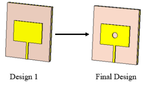
Figure 1. Design steps of the RMPA.
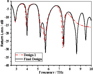
Figure 2. S11 for various designs.
To enhance the antenna's performance, especially its bandwidth and resonance characteristics, a circular slot is added to the center of the patch in the final design. This modification creates additional current paths and alters the effective dielectric environment, leading to better impedance matching and multiple resonances. The S11 response indicates that the final design (represented solid line) achieves deeper and broader resonances compared to the initial design (shown by the red dashed line), signifying improved bandwidth and return loss performance. This optimization illustrates the effectiveness of slot loading in fine-tuning and enhancing the characteristics of microstrip antennas for advanced wireless communication applications.
2.2. Parametric Analysis
This section explores the outcomes of the parametric study, focusing on how various factors influence the antenna's performance. In particular, it examines the effects of different substrate materials, variations in substrate thickness, feed widths and circle radius on the antenna's performance. The study provides key insights into optimizing antenna design for improved functionality by analyzing these parameters. The results highlight the importance of selecting appropriate materials, substrate thicknesses, feed width, and radius of circle to achieve optimal performance across the intended frequency ranges.
2.2.1. Changes in Substrate Thicknesses
This section of the study analyses the impact of varying substrate thicknesses on the antenna's performance. Thicknesses of 3.0 µm, 3.3 µm, and 4.5 µm were appropriate to evaluate their influence on return loss and overall effectiveness. The results are depicted in Figure 3, with the data outlined in Table 2. The analysis shows that the antenna performed best with a substrate thickness of 3.3 µm, achieving the lowest return loss, which signifies reduced signal reflection and improved efficiency. These results underscore the importance of selecting the appropriate substrate thickness to enhance antenna performance, particularly in minimizing return loss and optimizing signal transmission.
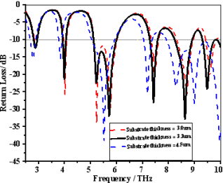
Figure 3. S11 for different substrate thicknesses.
Table 2. Comparison table for different substrate thicknesses.

Substrate thickness (µm)

Resonance frequency (THz)

Return loss (dB)

3.0

2.9, 4.02, 5.24, 7.48, 8.7, 9.59

-11.9, -27.2, -35.58, -20.75, -26.27, -20.39

3.3

2.87, 3.98, 5.71, 7.41, 8.63, 9.49

-12.45, -21.76, -32.36, -28.86, -33.67, -24.34

4.5

2.78, 3.83, 5.53, 7.19, 9

-15.43, -15.74, -39.71, -25.2, -28.66

2.2.2. Changes in Substrate Materials
This section examines the effects of different substrate materials on the antenna's performance, specifically evaluating Rogers RT5880, FR-4, and Quartz.
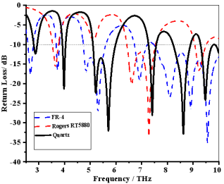
Figure 4. S11 for various substrate materials.
These materials were tested to determine their impact on return loss and overall performance. Each substrate material has distinct electrical and mechanical properties influencing signal propagation and antenna behavior. The results are visually represented in Figure 4, with detailed performance data summarized in Table 3. The analysis showed that Quartz provided the best performance, yielding the lowest return loss, which indicates better impedance matching and enhanced signal transmission. These findings emphasize the critical role of substrate material selection in antenna design, demonstrating its potential to improve functionality and overall performance.
2.2.3. Effect of Feed Line Width on Antenna Performance
This section analyzes the influence of varying feed line widths on the antenna’s return loss and resonant characteristics. Three feed widths, 1 µm, 2.5 µm, and 4 µm, were examined to assess their effect on impedance matching and multiband behavior. As illustrated in Figure 5 and detailed in Table 4, the feed line width of 2.5 µm yields the most favorable results, exhibiting strong return loss across six distinct resonant frequencies. In contrast, the narrower feed (1 µm) leads to suboptimal impedance matching and weaker return loss at certain bands, while the wider feed (4 µm) results in a decreased number of resonant modes. These findings highlight the critical role of feed line optimization in achieving efficient multiband performance.
Table 3. Comparison table for various substrate materials.

Substrate materials

Resonance frequency (THz)

Return loss (dB)

Quartz

2.87, 3.98, 5.71, 7.41, 8.63, 9.49

-12.45, -21.76, -32.36, -28.86, -33.67,-24.34

FR-4

2.68, 3.73, 5.31, 6.92

-17.98, -16.84, -27.28,-19.1

Rogers RT5880

3.64, 7.29, 9.24

-15.89, -33.94, -16.83

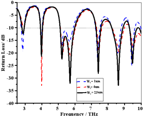
Figure 5. S11 for the various feed widths.
2.2.4. Influence of Circular Slot Radius on Resonant Characteristics
The radius of the circular slot introduced in the patch significantly influences the antenna’s resonant behavior by modifying current distribution and electromagnetic coupling. Slot radii of 1.6 µm, 3.3 µm, and 3.5 µm were investigated to evaluate their effect on return loss. The results, presented in Figure 6 and summarized in Table 5, indicate that a radius of 3.3 µm offers the most favorable performance, producing six distinct resonant frequencies with deeper return loss values, signifying improved impedance matching. In comparison, the smaller radius (1.6 µm) resulted in fewer resonances with higher reflection levels, while the larger radius (3.5 µm) caused slight frequency shifts and reduced performance, particularly at higher frequency bands.
Table 4. Comparison table for various feed widths.

Feed width (µm)

Resonance frequency (THz)

Return Loss (dB)

1

2.84, 3.98, 5.19, 7.38, 8.59, 9.44

-19.11, -14.33, -19.98, -23.89, -20.15,-25.11

2.5

2.87, 3.98, 5.71, 7.41, 8.63, 9.49

-12.45, -21.76, -32.36, -28.86, -33.67, -24.34

4

3.99, 5.25, 7.46, 8.68

-35.96, -21.83, -19.12,-19.97

Table 5. Comparison table for various radius of circles.

Circle radius (µm)

Resonance frequency (THz)

Return Loss (dB)

1.6

2.90, 3.95, 5.67, 7.33

-13.07, -20.21, -25.54, -17.39,

3.3

2.87, 3.98, 5.71, 7.41, 8.63, 9.49

-12.45, -21.76, -32.36, -28.86, -33.67, -24.34

3.5

2.87, 3.99, 5.71, 7.44

-12.33, -22.37, -25.86, -30.73

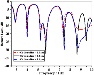
Figure 6. S11 for the different radius of the circle.
2.3. Proposed Antenna
This section investigated a circular split rectangular microstrip patch antenna, operating in the 2.5 to 10 THz range for Terahertz applications. Copper was used as the conductive and ground material, with a quartz substrate to enhance efficiency and bandwidth. This design and material choice optimized the antenna's functionality across the specified frequency range. The parameters of the designed RMPA are shown in Table 6, and the dimensions are shown in Figure 7 (a, b).
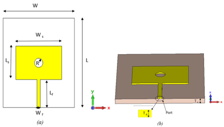
Figure 7. Figure Proposed RMPA with dimensions: (a) Front view; (b) Perspective view.
Table 6. Dimensions of the designed RMPA.

Parameter

Value (µm)

W

56

L

64

Wf

2.5

Lf

20

Ws

36

Ls

24

R

3.3

Tp

1

Ts

3.3

∈r

3.75

3. Results
This section describes the development and testing of the antenna utilizing CST Microwave Studio v2019, focusing particularly on the simulation results. The antenna's performance is assessed using several key parameters, including return loss, Voltage Standing Wave Ratio (VSWR), efficiency, bandwidth, 3D radiation patterns, and antenna gain.
3.1. Return Loss (S11)
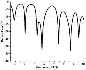
Figure 8. Simulated return loss (S11 in dB) of the proposed RMPA across the six resonant frequencies.
The simulation results for the proposed RMPA demonstrate return loss at six resonant frequencies: 2.87 THz, 3.98 THz, 5.71 THz, 7.42 THz, 8.63 THz, and 9.49 THz. The corresponding bandwidths for these frequencies are 0.14 THz, 0.13 THz, 0.88 THz, 0.31 THz, 0.68 THz, and 0.53 THz, as illustrated in Figure 8. The return loss values at these resonant frequencies are -12.44 dB, -21.76 dB, -32.36 dB, -28.59 dB, -33.06 dB, and -24.34 dB, respectively. These results confirm excellent impedance matching, particularly at higher frequencies, and validate the antenna’s ability to operate efficiently across a wide range of THz bands.
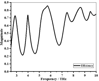
Figure 9. Radiation efficiency (%) of the proposed RMPA at each resonant frequency.
3.2. Efficiency
The simulation results for the proposed RMPA indicate that the efficiency at the resonant frequencies is recorded at 76.26%, 75.38%, 85.95%, 78.53%, 84.24%, and 78.62% at frequencies of 2.87 THz, 3.98 THz, 5.71 THz, 7.42 THz, 8.63 THz, and 9.49 THz, respectively, as shown in Figure 9. These values demonstrate a diverse range of efficiency performance across the various resonant frequencies, highlighting the antenna's ability to maintain effective efficiency in different frequency bands. Notably, the higher efficiencies observed at frequencies of 5.71 THz and 8.63 THz, such as 85.95% and 84.24%, suggest that the antenna can provide strong signal strength, making it well-suited for applications requiring reliable performance across multiple frequency ranges.
3.3. Vswr
The VSWR is a critical parameter that reflects how efficiently power is transmitted from the feed line to the antenna. Ideally, a VSWR value close to 1 indicates minimal reflection and optimal power transfer. The simulated VSWR values for the proposed RMPA at the six resonant frequencies 2.87 THz, 3.98 THz, 5.71 THz, 7.42 THz, 8.63 THz, and 9.49 THz are 1.63, 1.18, 1.05, 1.08, 1.05, and 1.13, respectively, as illustrated in Figure 10. All values are below the industry-accepted threshold of 2.0, confirming excellent impedance matching across all operating bands. These results affirm that the proposed antenna design efficiently radiates power with minimal signal reflection, making it suitable for high-frequency THz systems.
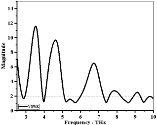
Figure 10. VSWR of the proposed RMPA.
3.4. Directivity
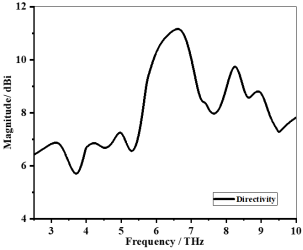
Figure 11. Directivity (in dBi) of the proposed RMPA at the six resonant frequencies.
The Directivity measures the antenna's ability to focus energy in a specific direction when compared to an isotropic radiator. High directivity is essential for targeted transmission and reception in THz applications such as radar and sensing. The simulated directivity values for the proposed RMPA at the resonant frequencies are 6.73 dBi (2.87 THz), 6.65 dBi (3.98 THz), 9.06 dBi (5.71 THz), 8.46 dBi (7.42 THz), 8.48 dBi (8.63 THz), and 7.32 dBi (9.49 THz), as shown in Figure 11. These values demonstrate strong directional radiation patterns, especially at higher frequency bands. The high directivity enhances system performance by improving spatial resolution and reducing interference from undesired directions, thereby confirming the antenna's potential for high-resolution THz imaging and detection systems.
3.5. Gain
The simulation results for the proposed RMPA indicate that the gain at the resonant frequencies 2.87 THz, 3.98 THz, 5.71 THz, 7.42 THz, 8.63 THz, and 9.49 THz is measured at 5.71 dBi, 5.46 dBi, 8.41 dBi, 7.41 dBi, 7.74 dBi, and 6.29 dBi, respectively, given in Figure 12. These values exhibit a varied range of gain performance across the different resonant frequencies, demonstrating the antenna's ability to maintain effective gain across multiple frequency bands. Notably, the higher gains observed at frequencies such as 8.41 dBi and 7.74 dBi suggest that the antenna can provide strong signal strength, making it well-suited for applications requiring reliable performance across diverse frequency ranges.
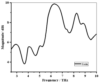
Figure 12. Gain (in dBi) of the proposed RMPA.
3.6. 3D Radiation Pattern
The radiation pattern of the proposed patch antenna at frequencies of 2.87 THz, 3.98 THz, 5.71 THz, 7.42 THz, 8.63 THz, and 9.49 THz is depicted in Figure 13(a, b, c, d, e, f). These figures showcase both the 3D radiation patterns, with the antenna's structure incorporated into the 3D representation for enhanced clarity. This visualization indicates that the emitted power is primarily directed vertically, leading to an increase in gain. Additionally, two smaller lobes are present on either side, exhibiting significantly lower power levels.
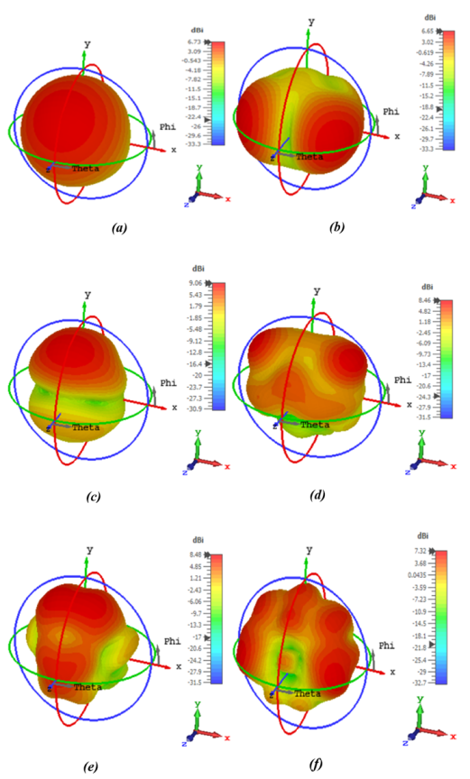
Figure 13. 3D radiation patterns of the proposed RMPA at resonant frequencies: (a) 2.87 THz, (b) 3.98 THz, (c) 5.71 THz, (d) 7.42 THz, (e) 8.63 THz, and (f) 9.49 THz.
3.7. Surface Current
The surface current distribution provides critical insight into how electromagnetic energy propagates and radiates across the antenna structure. Figure 14 presents the simulated surface current distributions of the proposed RMPA at its six resonant frequencies. At each frequency 2.87 THz, 3.98 THz, 5.71 THz, 7.42 THz, 8.63 THz, and 9.49 THz, the current is observed to be concentrated primarily around the edges of the patch and near the slot regions. These concentrated regions indicate strong radiating zones, contributing to the multiband operation of the antenna. The variation in current intensity and distribution across different frequencies highlights the effectiveness of the slot-loaded design in supporting multiple resonant modes. This analysis validates the antenna's structural design and confirms its suitability for efficient multiband THz radiation.
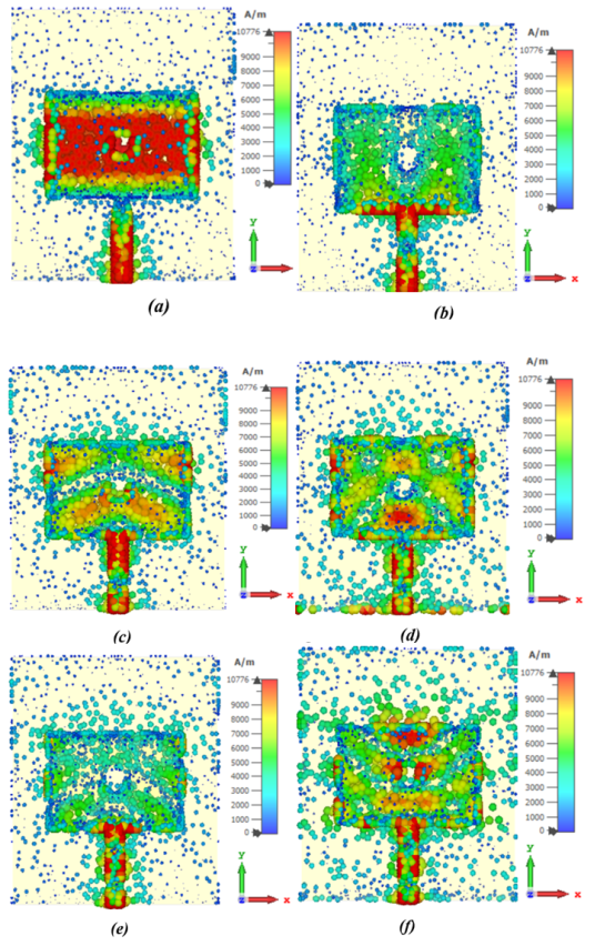
Figure 14. Surface current distribution of the proposed RMPA at resonant frequencies: (a) 2.87 THz, (b) 3.98 THz, (c) 5.71 THz, (d) 7.42 THz, (e) 8.63 THz, and (f) 9.49 THz.
Table 7. The overall results of the designed hexa-band RMPA.

Frequency (THz)

S11 (dB)

Bandwidth (GHz)

Gain (dBi)

Directivity (dBi)

VSWR

Efficiency (%)

2.87

-12.44

140

5.71

6.73

1.63

76.26

3.98

-21.76

130

5.46

6.65

1.18

75.38

5.71

-32.36

880

8.41

9.06

1.05

85.95

7.42

-28.59

310

7.41

8.46

1.08

78.53

8.63

-33.06

680

7.74

8.48

1.05

84.24

9.49

-24.34

530

6.29

7.32

1.13

78.62

4. Discussion
The proposed RMPA outperforms the other antennas in Table 8 by offering a more compact design (56 × 64 µm²), while supporting six distinct frequency bands, compared to the one or two bands in most references.
Table 8. Comparison with recent work.

Ref.

Size (µm2)

S11 (dB)

No. of bands

Efficiency

Bandwidth (GHz)

Gain (dBi)

VSWR

Fabrication complexity

Year

56.8×66.8

-19.30

3

-

140

6.1

-

Precise fabrication risk

2021

-29.20

700

6.3

-22.50

410

6.8

190 ×130

-27.70

1

98.38%

10.4

-

-

Advanced material (graphene), high cost

2022

300 ×300

-16.00

1

80%

415

5.87

-

Larger size, high cost, and precise fabrication risk

2022

1000×1200

-16.19

2

-

9.53

5.17

-

Larger size, high cost, complex design

2024

-24.27

24.19

3.19

Proposed

56×64

-12.44

6

76.26%

140

5.71

1.63

Compact size, conventional material, simple design

-

-21.76

75.38%

130

5.46

1.18

-32.36

85.95%

880

8.41

1.05

-28.59

78.53%

310

7.41

1.08

-33.06

84.24%

680

7.74

1.05

-24.34

78.62%

530

6.29

1.13

It delivers superior bandwidth, with a peak of 880 GHz, significantly higher than the others, and achieves excellent return loss (S11 = -33.06 dB), indicating better impedance matching. Additionally, the RMPA demonstrates higher gain, reaching 8.41 dBi, surpassing the gain of other antennas. These advantages make it highly suitable for modern communication systems, where space-saving, wideband, and high-performance antennas are essential for efficient and reliable operation. The proposed design is feasible for fabrication using current micro fabrication technologies. The antenna's simple single-layer structure, standard materials (copper and quartz), and coaxial feeding reduce manufacturing complexity. Its compact size can be reliably fabricated using standard photolithography or electron-beam lithography, which provide the necessary precision at the micrometer scale. This makes the design both cost-effective and practical for THz applications.
5. Application Suitability: Radar and Remote Sensing
Among the wide range of THz applications, radar and remote sensing systems demand antennas with high gain (typically >6 dBi), wide bandwidth for enhanced range resolution, and stable radiation patterns for accurate detection. The proposed RMPA meets these criteria by providing gains up to 8.41 dBi, bandwidths as wide as 880 GHz, and high efficiency (>75%) across all resonant bands. These characteristics ensure high spatial resolution, better signal-to-noise ratio, and reliable detection capability, which are critical for terahertz imaging and environmental monitoring. The compact size also makes the antenna suitable for integration into portable or chip-scale sensing systems. Therefore, the proposed design is particularly well-suited for high-resolution THz radar and remote sensing applications. These are critical for terahertz imaging and environmental monitoring. The compact size also makes the antenna suitable for integration into portable or chip-scale sensing systems. Therefore, the proposed design is particularly well-suited for high-resolution THz radar and remote sensing applications .
6. Conclusions
In this study, a compact rectangular microstrip patch antenna (RMPA) was designed and evaluated for terahertz (THz) applications. The proposed antenna demonstrates strong performance across six distinct resonant frequencies, offering high gain (up to 8.41 dBi), wide bandwidth (up to 880 GHz), and efficient operation (up to 85.95%). Additionally, the antenna exhibits favorable VSWR values (all below 2), low return loss, and consistent radiation characteristics across bands. The design also addresses typical THz fabrication challenges through its simple single-layer structure, use of standard materials, and compact footprint, enhancing its feasibility for manufacturing. While the antenna shows promising characteristics for THz systems such as radar, remote sensing, and spectroscopy, future experimental validation is recommended to confirm real-world applicability.
7. Future Work
To strengthen the practical relevance of the proposed RMPA, future research will focus on several key areas. First, experimental fabrication and measurement of the antenna using micro-fabrication techniques will be conducted to validate simulation results. This includes evaluating performance metrics such as gain, bandwidth, and return loss in a real-world THz testing environment. Second, further optimization of the antenna geometry and feeding techniques will be explored to enhance multi-band performance, minimize losses, and improve radiation efficiency. Finally, the use of advanced materials such as graphene, metamaterials, or flexible substrates will be investigated to enable tunability, reduce size further, and expand the range of THz applications. These developments aim to make the antenna more adaptable for integration into next-generation terahertz systems.
Abbreviations

RMPA

Rectangular Microstrip Patch Antenna

CST

Computer Simulation Technology

IoT

Internet of Things

THz

Terahertz

MPA

Microstrip Patch Antenna

WNoC

Wireless Network-on-Chip

MEMS

Micro-electro-mechanical Systems

VSWR

Voltage Standing Wave Ratio

S11

Return Loss

Author Contributions
Mohammad Alim Uddin: Conceptualization, Software, Methodology, Investigation, Supervision Writing – review & editing
Mohammad Mesbahul Islam: Data curation, Software, Writing – original draft, Formal Analysis
Monoara Khatun: Data curation, Visualization, Investigation
Mistress Sumaiya Akter Smrity: Resources, Validation, Investigation
Funding
This work is not supported by any external funding.
Data Availability Statement
The data supporting the outcome of this research work has been reported in this manuscript.
Conflicts of Interest
The authors declare no conflicts of interest.
References
[1] Song, H. J., Nagatsuma, T. Present and future of terahertz communications. IEEE Trans. Terahertz Sci. Technol. 2011, 1, 256-263.
[2] Koenig, S., Lopez-Diaz, D., Antes, J., Boes, F., Henneberger, R., Leuther, A., Tessmann, A., Schmogrow, R., Hillerkuss, D., Palmer, R. Wireless sub-THz communication system with high data rate. Nat. Photonics 2013, 7, 977-981.
[3] Akyildiz, I. F., Jornet, J. M., Han, C. Terahertz band: Next frontier for wireless communications. Phys. Commun. 2014, 12, 16-32.
[4] He, Y., Chen, Y., Zhang, L., Wong, S.-W., Chen, Z. N. An overview of terahertz antennas. China Commun. 2020, 17, 124165.
[5] Li, B., Long, Y., Liu, H., Zhao, C. Research progress on Terahertz technology and its application in agriculture. Trans. Chin. Soc. Agric. Eng. 2018, 34, 1-9.
[6] Deb, S., Ganguly, A., Pande, P. P., Belzer, B., Heo, D. Wireless NoC as interconnection backbone for multicore chips: Promises and challenges. IEEE J. Emerg. Sel. Top. Circuits Syst. 2012, 2, 228-239.
[7] Nishizawa, J., Sasaki, T., Suto, K., Yamada, T., Tanabe, T., Tanno, T., Sawai, T., Miura, Y. THz imaging of nucleobases and cancerous tissue using a GaP THz-wave generator. Opt. Commun. 2005, 244, 469-474.
[8] Naftaly, M., Foulds, A. P., Miles, R. E., Davies, A. G. Terahertz transmission spectroscopy of nonpolar materials and relationship with composition and properties. Int. J. Infrared Millimeter Waves 2005, 26, 55-64.
[9] Khan, M. A. K., Ullah, M. I., Kabir, R., Alim, M. A. High-performance graphene patch antenna with superstrate cover for terahertz band application. Plasmonics 2020, 15, 1719-1727.
[10] Gonzalez, A., Kaneko, K., Kojima, T., Asayama, S., Uzawa, Y. Terahertz corrugated horns (1.25–1.57 THz): Design, Gaussian modeling, and measurements. IEEE Trans. Terahertz Sci. Technol. 2016, 7, 42-52.
[11] Mak, K.-M., So, K.-K., Lai, H.-W., Luk, K.-M. A magnetoelectric dipole leaky-wave antenna for millimeter-wave application. IEEE Trans. Antennas Propag. 2017, 65, 6395-6402.
[12] Han, K., Nguyen, T. K., Park, I., Han, H. Terahertz Yagi-Uda antenna for high input resistance. J. Infrared Millim. Terahertz Waves 2010, 31, 441-454.
[13] Alharbi, K. H., Khalid, A., Ofiare, A., Wang, J., Wasige, E. Diced and grounded broadband bow-tie antenna with tuning stub for resonant tunneling diode terahertz oscillators. IET Microw. Antennas Propag. 2016, 11, 310-316.
[14] Abdulnabi, H. A., Hussein, R. T., Fyath, R. S. 0.1-10 THz single port log periodic antenna design based on Hilbert graphene artificial magnetic conductor. ARPN J. Eng. Appl. Sci. 2017, 12.
[15] Guo, L., Huang, F., Tang, X. A novel integrated MEMS helix antenna for terahertz applications. Optik 2014, 125, 101-103.
[16] Rappaport, T. S., Heath Jr, R. W., Daniels, R. C., Murdock, J. N. Millimeter Wave Wireless Communications; Pearson Education, 2015.
[17] Nandalal, V., Kumar, V. A., Sumalatha, M. S., Manikandan, T. Performance Evolution of Reconfigurable Antenna Using Contact and Non-Contact Feeding Technique. 2019 3rd Int. Conf. Electron. Commun. Aerosp. Technol. (ICECA) 2019, 952-954.
[18] Sarkar, B. D., Shankar, S., Thakur, A., Chaurasiya, H. Resonant frequency determination of rectangular patch antenna using Neural Network. 2015 1st Int. Conf. Next Generation Comput. Technol. (NGCT) 2015, 915-917.
[19] George, J. N., Madhan, M. G. Analysis of single band and dual band graphene-based patch antenna for the terahertz region. Physica E 2017, 94, 126-131.
[20] Hassan, S. K., Sallomi, A. H., Wali, M. H. Loaded notched dual compact rectangular ultra-wideband applications monopole antenna. Telkomnika (Telecommun. Comput. Electron. Control) 2023, 21, 506-512.
[21] Thaher, R. H., Alsaidy, S. N. New compact pentagonal microstrip patch antenna for wireless communications applications. Am. J. Electromagn. Appl. 2015, 6, 53-64.
[22] Shaddad, R. Q., Aqlan, E. A., Abdo, E. A., Almogahed, M. A., Alglal, A. M., Abdullah, W. A. High bandwidth triple-band microstrip patch antenna for THz applications. 2021 1st Int. Conf. Emerg. Smart Technol. Appl. (eSmarTA) 2021, 1-5.
[23] Jeyakumar, P., Anandpushparaj, J., Thanapal, P., Meenatchi, S., Dhamodaran, M. Terahertz microstrip patch antenna design and modelling for 6G mobile communication. J. Electr. Eng. Technol. 2023, 18, 2253-2262.
[24] Khan, W. A., Muhammad, A. B. Design and analysis of wideband THz micro-size patch antenna for 6G application. 2022 6th Int. Conf. Millimeter-Wave Terahertz Technol. (MMWaTT) 2022, 1-4.
[25] Amraoui, Y., Halkhams, I., El Alami, R., Jamil, M. O., Qjidaa, H. High gain MIMO antenna with multiband characterization for terahertz applications. Sci. Afr. 2024, 26, e02380.
[26] Federici, J. F., Schulkin, B., Huang, F., Gary, D., Barat, R., Oliveira, F., Zimdars, D. THz imaging and sensing for security applications—explosives, weapons and drugs. Semicond. Sci. Technol. 2005, 20(7), S266–S280.
Cite This Article
  • APA Style

    Uddin, M. A., Islam, M. M., Khatun, M., Smrity, M. S. A. (2025). High Performance Hexa Band Compact Microstrip Patch Antenna Design for Terahertz Applications. Journal of Electrical and Electronic Engineering, 13(4), 154-167. https://doi.org/10.11648/j.jeee.20251304.12

    Copy | Download

    ACS Style

    Uddin, M. A.; Islam, M. M.; Khatun, M.; Smrity, M. S. A. High Performance Hexa Band Compact Microstrip Patch Antenna Design for Terahertz Applications. J. Electr. Electron. Eng. 2025, 13(4), 154-167. doi: 10.11648/j.jeee.20251304.12

    Copy | Download

    AMA Style

    Uddin MA, Islam MM, Khatun M, Smrity MSA. High Performance Hexa Band Compact Microstrip Patch Antenna Design for Terahertz Applications. J Electr Electron Eng. 2025;13(4):154-167. doi: 10.11648/j.jeee.20251304.12

    Copy | Download

  • @article{10.11648/j.jeee.20251304.12,
      author = {Mohammad Alim Uddin and Mohammad Mesbahul Islam and Monoara Khatun and Mistress Sumaiya Akter Smrity},
      title = {High Performance Hexa Band Compact Microstrip Patch Antenna Design for Terahertz Applications
    },
      journal = {Journal of Electrical and Electronic Engineering},
      volume = {13},
      number = {4},
      pages = {154-167},
      doi = {10.11648/j.jeee.20251304.12},
      url = {https://doi.org/10.11648/j.jeee.20251304.12},
      eprint = {https://article.sciencepublishinggroup.com/pdf/10.11648.j.jeee.20251304.12},
      abstract = {Designing the multiband antenna presented considerable challenges, requiring meticulous optimization to ensure consistent performance across multiple frequency ranges. This research introduces an innovative rectangular microstrip patch antenna (RMPA) that operates as a hexa-band in the terahertz (THz) frequency spectrum. The antenna's compact physical dimensions are 56×64×3.3 µm³, and it is constructed using a Quartz (Fused) substrate with a dielectric constant (𝜀𝑟) of 3.75. The radiating patch and ground plane layers are made from copper. This antenna resonates at six distinct frequencies: 2.87 THz, 3.98 THz, 5.71 THz, 7.42 THz, 8.63 THz, and 9.49 THz. The bandwidths are 140 GHz, 130 GHz, 880 GHz, 310 GHz, 680 GHz, and 530 GHz; the efficiencies are 76.26%, 75.38%, 85.95%, 78.53%, 84.24%, and 78.62%; and gains are at 5.71 dBi, 5.46 dBi, 8.41 dBi, 7.41 dBi, 7.74 dBi, and 6.29 dBi at resonance frequency, respectively. Simulations performed using Computer Simulation Technology (CST) Software (version 2019) confirm the antenna’s high efficiency and gain. With its flexible design and verified performance, this antenna is well-suited for a wide range of wireless applications, including radar, space science, sensing, and high-speed communication.},
     year = {2025}
    }
    

    Copy | Download

  • TY  - JOUR
    T1  - High Performance Hexa Band Compact Microstrip Patch Antenna Design for Terahertz Applications
    
    AU  - Mohammad Alim Uddin
    AU  - Mohammad Mesbahul Islam
    AU  - Monoara Khatun
    AU  - Mistress Sumaiya Akter Smrity
    Y1  - 2025/07/15
    PY  - 2025
    N1  - https://doi.org/10.11648/j.jeee.20251304.12
    DO  - 10.11648/j.jeee.20251304.12
    T2  - Journal of Electrical and Electronic Engineering
    JF  - Journal of Electrical and Electronic Engineering
    JO  - Journal of Electrical and Electronic Engineering
    SP  - 154
    EP  - 167
    PB  - Science Publishing Group
    SN  - 2329-1605
    UR  - https://doi.org/10.11648/j.jeee.20251304.12
    AB  - Designing the multiband antenna presented considerable challenges, requiring meticulous optimization to ensure consistent performance across multiple frequency ranges. This research introduces an innovative rectangular microstrip patch antenna (RMPA) that operates as a hexa-band in the terahertz (THz) frequency spectrum. The antenna's compact physical dimensions are 56×64×3.3 µm³, and it is constructed using a Quartz (Fused) substrate with a dielectric constant (𝜀𝑟) of 3.75. The radiating patch and ground plane layers are made from copper. This antenna resonates at six distinct frequencies: 2.87 THz, 3.98 THz, 5.71 THz, 7.42 THz, 8.63 THz, and 9.49 THz. The bandwidths are 140 GHz, 130 GHz, 880 GHz, 310 GHz, 680 GHz, and 530 GHz; the efficiencies are 76.26%, 75.38%, 85.95%, 78.53%, 84.24%, and 78.62%; and gains are at 5.71 dBi, 5.46 dBi, 8.41 dBi, 7.41 dBi, 7.74 dBi, and 6.29 dBi at resonance frequency, respectively. Simulations performed using Computer Simulation Technology (CST) Software (version 2019) confirm the antenna’s high efficiency and gain. With its flexible design and verified performance, this antenna is well-suited for a wide range of wireless applications, including radar, space science, sensing, and high-speed communication.
    VL  - 13
    IS  - 4
    ER  - 

    Copy | Download

Author Information
  • Electrical and Electronic Engineering, Dhaka University of Engineering & Technology (DUET), Gazipur, Bangladesh

    Biography: Mohammad Alim Uddin is a student at Dhaka University of Engineering & Technology, Electrical and Electronic Engineering Department. He completed his Bachelor's in Electrical and Electronic Engineering from Dhaka University of Engineering & Technology in 2024. He has authored and co-authored in multiple international and national research collaboration projects in recent years. He currently doing his Master of Science in Electrical and Electronic Engineering.

    Research Fields: Metamaterial, Antenna, Quantum materials, Quantum sensors, Nanomaterials

  • Electrical and Electronic Engineering, Dhaka University of Engineering & Technology (DUET), Gazipur, Bangladesh

    Biography: Mohammad Mesbahul Islam was born in Joypurhat, Bangla-desh, in 1998. He is an undergraduate (UG) student in the Depart-ment of Electrical and Electronic Engineering, Dhaka University of Engineering & Technology, Gazipur. He has participated in multiple international research work.

    Research Fields: Metamaterial, Antenna, RF

  • Electrical and Electronic Engineering, Dhaka University of Engineering & Technology (DUET), Gazipur, Bangladesh

    Biography: Monoara Khatun was born in 1997. She has completed her Bachelor of Science in Electrical and Electronic Engineering from Dhaka University of Engineering and Technology in 2024. Cur-rently, she is doing her Master's in Electrical and Electronic Engi-neering at Dhaka University of Engineering and Technology.

    Research Fields: Antenna, Microwave, RF

  • Electrical and Electronic Engineering, Dhaka International University (DIU), Dhaka, Bangladesh

    Biography: Mistress Sumaiya Akter Smrity was born in Kushtia, Bangla-desh, in 1999. She is an undergraduate (UG) student in the Depart-ment of Electrical and Electronic Engineering, Dhaka International University, Dhaka. She has participated in multiple international research projects.

    Research Fields: Metamaterial, Antenna, Quantum sensors