Research Article | | Peer-Reviewed

Theoretical Optimization of Performance Indicators for the Flat-plate Solar Collector of a Thermosiphon Solar Water Heater

Received: 2 March 2026     Accepted: 13 March 2026     Published: 28 March 2026
Views:       Downloads:
Abstract

Solar energy is currently one of the most promising sources for meeting global energy needs. Hot water production using solar water heaters represents one of the most promising applications of solar energy for countries like Burkina Faso. However, the efficiency of solar system performance indicators remains a challenge, especially during periods of low sunlight. Our work focuses on a numerical study of a flat-plate solar collector designed and tested at the Higher Teacher Training College (ENS) in Burkina Faso, at the Ouagadougou annex site. The objective of our work is to numerically optimize performance indicators such as efficiency and fluid temperature across several key solar collector parameters in order to improve the quality of the solar system applied to domestic hot water production. In this regard, the numerical results obtained indicate that an optimal efficiency value is achieved when the air gap is between 2 cm and 4 cm. Furthermore, a fiberglass insulation thickness of 8 to 15 cm at the rear is sufficient for optimal instantaneous output and maximum water temperature from the collector. Regarding the glass pane, we determined that 4 cm is the optimal value for performance. Additionally, a 1 cm gap between the tubes is necessary to optimize the performance indicators of our solar collector.

Published in Science Journal of Energy Engineering (Volume 14, Issue 1)
DOI 10.11648/j.sjee.20261401.13
Page(s) 21-31
Creative Commons

This is an Open Access article, distributed under the terms of the Creative Commons Attribution 4.0 International License (http://creativecommons.org/licenses/by/4.0/), which permits unrestricted use, distribution and reproduction in any medium or format, provided the original work is properly cited.

Copyright

Copyright © The Author(s), 2026. Published by Science Publishing Group

Keywords

Thermal, Water Heater, Solar Collector, Optimization

1. Introduction
Solar energy is currently one of the most promising sources for meeting energy needs in many countries, particularly those with high levels of sunshine. This energy has the advantage of being clean and renewable. A number of ways to improve the performance of CSIS systems have been proposed, including reducing absorber losses, increasing heat transfer, and improving the choice of materials. H. Taherian et al show that the instantaneous efficiency of the system decreases as the ratio of temperature to incident radiation increases. It is therefore recommended that the storage tank be designed so that the fluid entering the absorber is at a temperature close to that of the ambient temperature. In his study, O. Ketfi recommends improving the performance of a flat-plate water collector by ensuring good radiator-absorber adhesion and integrating a system to regulate the temperature at the inlet to the storage tank. The overall objective of this work is to improve the efficiency of the flat-plate solar collector digitally by optimizing the internal parameters that influence the performance of the solar collector, giving priority to locally available materials. Specifically, we studied:
1) The optimal thickness to optimize performance indicators
2) The air gap for optimal performance indicators
3) The optimal spacing between tubes to make the solar collector more efficient
2. Materials and Methods
The solar collector studied is a flat-plate glass collector designed and manufactured in Burkina Faso by a local company called Atelier Nikiema&frère. It was installed on the premises of the teacher training college in 2020. The water heater is a separate unit consisting of the solar collector and a storage tank. The solar collector consists of a casing, an absorbing plate, 12 parallel absorber tubes, single glazing, internal and external insulation, and heat transfer fluid circulating through the tubes and connection channels. The solar collector is mounted on the ground using a base.
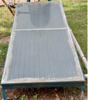
Figure 1. Flat-plate solar collector.
Table 1. Components of the solar water heater.

Collector

Galvanized steel

Glazing Clear glass

ransmissibility: τV= 83%

Reflexibility: 8%

Absorptivity: αV=9%

Tilt angle

15°

Collector dimensions

Length: L=2 m

Width: l=1 m

Gross surface area: S=2

Pipe dimensions

Length: Lt=1.80 m

Diameter DH: 15 mm

Diameter: dt=21 mm

Number: 12

Maximum operating temperature

Tmax=95°C

Table 2. Physical properties of solar collector components materials.

materials

Density (kg m-3)

Thickness (mm)

Thermal capacity (J kg-1 K-1)

water

1000

-

4180

Glass

2530

5

840

Absorbent plate

7800

1.5

470

Tube

7800

2

470

Internal insulation

40

30

840

Air

1.2

40

1006

Table 3. Thermal properties of solar collector components.

Glass

Absorbent plate

tube

Glass Wool

Heat transfer fluid

air

Viscosity dynamique (Pa·s)

-

-

-

1,00·10-3

1,81·10-5

absorptivity

0.02

0.95

0.95

-

-

conductivity (W m-1 K-1)

0.78

50

46.7

0.041

0.6

0.023

Emisivity

0.89

0.16

0.04

0.85

-

-

2.1. Physical Model and Equivalent Electrical Diagram
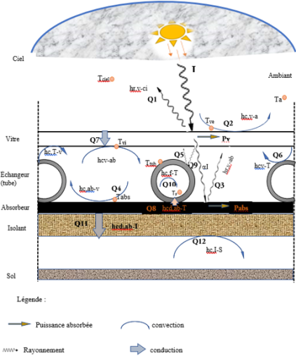
Figure 2. Physical model of the solar collector.
2.2. Energy and Thermal Balance
To establish the heat balance that reflects the behavior of our sensor, the nodal method was applied.
Energy balance of the outer surface of the window
12MvCpvdTvedt=hrciSvTci-Tve+hcvSvTa-Tve+hcdvSvTvi-Tve+αvIGSv(1)
Energy balance of the inner surface of the window
12MvCpvdTvidt=hrv-tSvTt-Tvi+hcv-tSvTt-Tvi+hcv-abSvTab-Tvi +hrv-tSvTab-Tvi+hcdvSvTvi-Tve(2)
Energy balance of the tube
MtCptdTtdt=hrt-vStTvi-Tt+hrab-tStTab-Tt+hct-vStTvi-Tt+hcdabStTab-Tt+hct-fAtTf-Tt+αtτvIGSt(3)
Energy balance of the heat transfer fluid
ρeCpeDh4dTfdt+ρeCpeṁDh4ndTfdx=hct-fAtTf-Tt(4)
Energy balance of the absorber plate
MabCpabdTabdt=hrab-vSabTvi-Tab+hrab-tSabTt-Tab+hcab-vSabTvi-Tab+hcdabStTt-Tab+hcdisAabTis-Tab+αabτvIGSab(5)
Energy balance of the internal insulation
MisCpisdTisdt=hcdis-bSisTb-Tis+hcdabSabTab-Tis(6)
Energy balance of the external insulation
MisCpisdTisdt=hcb-aSbTa-Tb+hcdbSbTis-Tb(7)
Calculation of heat transfer coefficients
The convective heat transfer coefficient of the air confined between the inner surface of the glass and the absorber plate.
hc,vi=hc,ab=hc,tub=λairNue1(8)
Pour l’air
Nu=0.06-0.017(β90)Gr1/3(9)
Gr=g.T.e13νair2.Ta(10)
Convective exchange coefficient of the heat transfer fluid hcf in the tubes dans les tubes.
hcf=Nu.λeauDH(11)
Nombre de Graetz: Gz=Re.Pr.DHL(12)
Nombre de Renolds: Re=ρeauvDHμeau(13)
Nombre de Prandtl: Pr=Cpμλ(14)
Laminar regime
Gz<100 Haussen
Nu=3.66+0.085×Gz1+0.047×Gz2/3×μeauμt0,14(15)
Radiative exchange coefficient between the outer surface of the glass and the sky.
hr,ve,ciel=σεvSvTve+TciTve2+Tci2(16)
he equivalent sky temperature as a function of the ambient temperature is given by:
Tci=0,0552Ta1,5(17)
The radiation exchange coefficient between the glass and the absorber
hr,vab=σTvi+TabTvi2+Tab21εv+1εab -1(18)
The radiation exchange coefficient between the absorber and the tube.
hr,abt=σTt+TabTt2+Tab21εt+1εab -1(19)
Conduction exchange coefficient at the glass.
hcd,v=λvev(20)
The power absorbed by the glass
Pv=αvIGSv(21)
The power absorbed by the tube
Ptub=αtubτvIGS'tub avec S'tub=3Stub (22)
The power absorbed by the absorber
Pab=αabτvIGSab(23)
The mass of the absorber: r:
Mab=ρabeabSab(24)
Thermal efficiency
The instantaneous (or thermal) efficiency of the flat-plate solar collector is equal to the ratio between the useful flux recovered and the total incident illumination received by the collector surface. .
η=QuSabIG(25)
Qu=ṁcpfTfs-Tfe
Output power = Power captured – Losses(26)
Qu: useful flux recovered by the heat transfer fluid (W).
Cpf: Specific heat of the heat transfer fluid (J/kg K).
Tfs: Fluid outlet temperature (K).
Tfe: Fluid inlet temperature (K).
Sab: Absorber surface area (m²).
IG: Solar irradiance (W/m²).
3. Results and Discussions
3.1. Changes in Water Temperature at the Sensor Outlet as a Function of Insulation Thickness
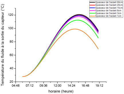
Figure 3. Temperature changes in the water at the sensor outlet as a function of the thickness of the insulation.
The thermal performance of a flat-plate solar collector depends on reducing heat loss to the environment. Among the design parameters, the thickness of the rear and side insulation plays a key role, as it controls conductive losses through the bottom wall, which account for a significant fraction of the overall loss coefficient. The temporal evolution of the drinking water outlet temperature for different thicknesses of glass wool ranging from 1 cm to 100 cm on a typical sunny day (Figure 3). All curves show a characteristic dynamic profile with significant differences in thermal amplitude depending on the thickness of the insulation. During the gradual increase in daily solar irradiance, the power absorbed by the solar collector exceeds the losses, which causes the temperature of the heat transfer fluid to rise. The regime is dominated by thermal inertia rather than losses. This transient behavior is typical for flat-plate collectors . There is a divergence in the curves after 12 noon. The temperature difference between 1 cm and 100 cm of insulation exceeds 14°C to 15°C, which is thermally significant and highlights that a significant portion of solar energy is dissipated backwards instead of being transferred to the fluid when the insulation thickness is low. These observations are consistent with the experimental work of . Subsequently, we see a plateau showing a phase of thermal saturation for thicknesses above 20 cm between 3 p.m. and 5 p.m. This demonstrates that even with very thick insulation (80 cm), the temperature increase becomes marginal because, although rear losses become negligible, the dominant losses now come from the glazing. This thermal saturation is widely documented in the literature . Finally, from 5 p.m. onwards, as solar irradiance weakens, losses dominate the energy received by the solar collector. This triggers a drop in temperature, but at a rate inversely proportional to the thickness of the insulation. Thus, insulation thicknesses between 10 cm and 15 cm are suitable for the optimal performance of the solar collector under study.
3.2. Change in Instantaneous Efficiency as a Function of Thickness
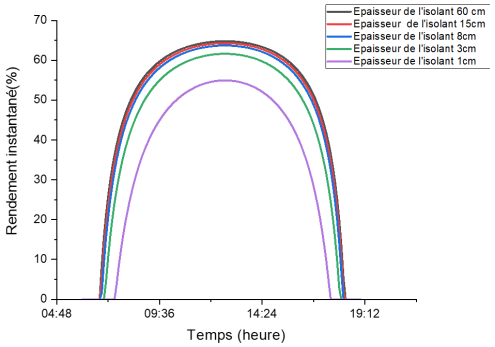
Figure 4. Change in instantaneous efficiency as a function of thickness.
The instantaneous thermal efficiency of the flat-plate solar collector as a function of solar time for different insulation thicknesses increases at the start of the day, reaching a maximum at midday, then declines symmetrically towards the evening (Figure 4). This behavior is well established for flat-plate collectors subjected to variable global radiation . The curves show that increasing the thickness of the insulation leads to a significant reduction in rear heat losses, resulting in a notable increase in maximum efficiency between 1 cm and 8 cm. Above 8 cm, the efficiency tends to saturate. This trend can be explained by a reduction in the overall heat loss coefficient as the insulation thickness increases, up to a limit beyond which losses are dominated by other mechanisms such as radiation or convection at the front of the collector rather than conduction at the rear . This saturation is consistent with the work of , which shows that in solar thermal systems, once a certain level of insulation is reached, additional gains are significantly reduced. Similarly, demonstrated that increasing insulation beyond a certain threshold slightly improves overall efficiency and is generally not justified from a thermo-economic point of view. The rate of growth observed in the morning characterizes the increase in overall solar radiation and a simultaneous reduction in the temperature gradient between the solar collector and its immediate environment. The decline (decrease) in the afternoon is symmetrical and can be explained by the decrease in solar irradiance, which causes an increase in losses due to a higher collector temperature than that of the ambient environment. At low irradiance, heat losses dominate, which limits efficiency . The curve corresponding to an insulation thickness of 1 cm shows a significant drop in maximum efficiency (55%) compared to greater thicknesses (63% to 65%). Increased conductive losses and higher residual heat flow are the basis for this difference in efficiency, as observed by Cenker et al. in poorly insulated flat-plate collectors, where conduction losses account for a significant portion of the solar energy intercepted. The marginal improvement in efficiency beyond approximately 8 cm to 15 cm of insulation is accompanied by a considerable increase in cost and bulk. Recent thermo-economic analyses show that the optimal thickness of insulation in a flat-plate collector is generally between 8 cm and 12 cm for domestic solar systems, as beyond this, the additional cost of insulation exceeds the energy gain obtained. This analysis is essential for the design of systems adapted to local constraints (cost, available materials, ease of construction). Recent models explicitly include these terms, showing that rear insulation plays a decreasing role when the thickness exceeds a certain threshold.
3.3. Optimal Air Gap
3.3.1. Instantaneous Efficiency as a Function of Air Gap
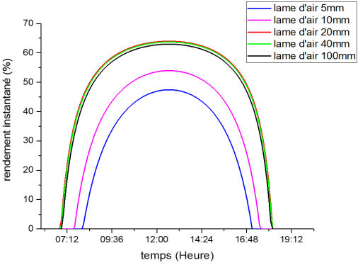
Figure 5. Instantaneous efficiency as a function of air gap.
Figure 5 illustrates the change in instantaneous efficiency of a flat-plate solar collector for different air gap thicknesses. For air gaps of less than 2 cm, the efficiency is low (less than 54%). This indicates that insulation becomes ineffective when the air gap is small, as forward losses become significant. Furthermore, for an air gap greater than 4 cm, the gain is negligible, also showing considerable forward losses induced by internal natural convection. Thus, we note that for an air gap value between 2 cm and 4 cm, the curves are almost identical, with a maximum of around 63%, which reveals that the increase in the air gap for efficiency must be limited to a certain threshold. This threshold represents the optimum value for the air gap. This result is corroborated by studies in the literature. .
3.3.2. Fluid Temperature as a Function of the Air Gap
In Figure 6, the temperature curves show a steady increase between 6 a.m. and 12 p.m. This period corresponds to the continuous evolution of global incident radiation. During this phase, the temperature of the absorber (absorbent plate + tubes) increases, causing an intensification of the natural flow of the thermosiphon linked to the temperature gradient. A broad peak is observed between 1 p.m. and 2 p.m. At this time, all temperatures are at their maximum, with notable differences depending on the air gap, following a given order. At this level, the observed order highlights an optimal air gap value of between 2 cm and 4 cm. After the peak, the curves decrease at illegal rates, especially for 10 cm. This confirms that the heat losses previously linked to natural internal convection at the air gap level intensify when the air gap value exceeds the optimal threshold.
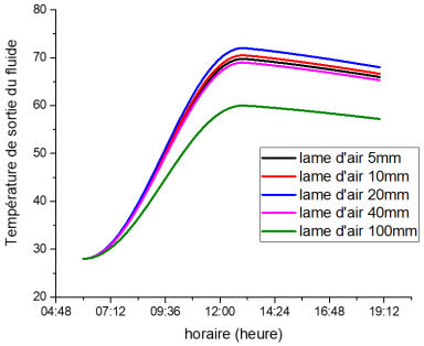
Figure 6. Fluid temperature as a function of the air gap.
3.4. Optimal Spacing Between Tubes
3.4.1. Collector Efficiency as a Function of the Spacing Between Absorber Tubes
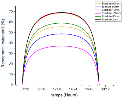
Figure 7. Collector efficiency as a function of the spacing between absorber tubes.
The change in instantaneous efficiency over time for different distances between the tubes in which the heat transfer fluid circulates is shown in Figure 7. Efficiency decreases significantly as the distance between the tubes increases, especially between 12 p.m. and 2 p.m. This change coincides with that of solar radiation. From these observations, we can say that heat loss and thermal resistance increase with spacing, which leads to a decrease in heat transfer to the fluid in our water. As a result, efficiency becomes low. Thus, according to Duffie et al. , the efficiency of the collector depends heavily on the thermal contact between the absorber plate and the fluid tubes. Poor adhesion or excessive spacing increases thermal resistance and reduces performance. We can therefore conclude that the air gap mainly influences upper heat losses and that the gap between the absorber tubes directly influences internal transfer to the fluid. .
3.4.2. Temperature of the Fluid Leaving the Solar Collector as a Function of the Distance Between the Absorber Tubes
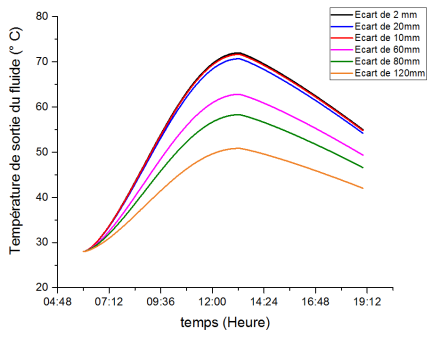
Figure 8. Temperature of the fluid leaving the solar collector as a function of the distance between the absorber tubes.
The temperature profile of the fluid at the outlet of the solar collector is strictly biphasic (Figure 8). There is an ascending phase before 12 noon and a descending phase after 2 p.m. Between 12 noon and 2 p.m., there is a slight peak. In addition, a temperature difference of approximately 22°C is observed between 0.2 cm and 12 cm. This considerable variation highlights the predominant role of internal thermal coupling between the fluid and the absorbing tube. The gap between the tubes has a thermal resistance effect between the absorbing tube and the heat transfer fluid. However, internal thermal resistances are inversely proportional to the collector efficiency factor F'. These results are therefore consistent with those in the literature, where it is estimated that any increase in thermal resistance between the absorbing plate and the fluid reduces the heat evacuation factor and thus lowers the temperature of the fluid at the outlet . Overall, a gap of 1 cm is necessary to optimize the performance indicators of our solar collector.
4. Conclusion
In this work, a theoretical model is proposed to predict the thermo-hydraulic performance of a flat-plate solar collector. The mathematical simulation of a solar water heating system, given the complexity of the heat transfer equations in the collector, requires simplifying assumptions. During this work, the performance indicators of the solar collector were theoretically optimized based on insulation, the air gap, and the distance that must be maintained between parallel tubes for efficient use of solar water heaters in domestic hot water production.
Abbreviations

ENS

Ecole Normale Superieur

hc

Convection Coefficient and the Tube

hct-f

Between the Tube and the Heat Transfer Fluid

hcb-a

Between the External Insulation and the Ambient Air

e1

Distance Between the Glass and the Absorber [m]

λair

Thermal Conductivity of Air [W.m-1.K-1]

Nu

Average Nusselt Number

Gr

Grashoff Dimensionless Number

νair

Kinematic Viscosity of Confined Air [m2.s-1]

g

Acceleration Due to Gravity [m.s-2]

The Difference Between the Respective Temperatures of the Upper Surface of the Absorber and the Inner Surface of the Glass [K].

Ta

Ambient Temperature [K]

 Re

Reynolds Numbe

Pr

Prandtl Numbe

eis

Thickness of the Insulation [m]

λis

Thermal Conductivity of the Insulation [W.m-2.K-1]

Thickness of the Glass [m]

Thermal Conductivity of the Glass [W.m-1.K-1]

Ptub

Power Absorbed by the Tube

Pab

Power Absorbed by the Absorber

Stub

Surface Area of the Tubes

Mab

Mass of the Absorber

Is

Solar Radiation (W/m²)

β

Optical Factors (%)  

κ

Thermal Transmission Coefficient (W /m².K)

Tm

Average Temperature of the Collector (K)

T t

Ambient Temperature (K)

Te

Sensor Inlet Temperature (K)

Ts

Sensor Outlet Temperature (k)

α

Absorber Absorption Rate (%)

τ

Glazing Transmission Rate (%)

Tve

External Glass Temperature (°C)

Tvi

Internal Glass Temperature (°C)

Ttub

Ube Temperature (°C)

Tabs

Absorber Temperature (°C)

Tec

Temperature of Water Entering the Sensor (°C)

Tsc

Temperature of Water Leaving the Sensor (°C)

Tf

Cold Water Temperaturee(°C)

V

Volume Representing Requirements in L/j

C

Power Representing Requirements in kwh/day

Tc

Hot Water Temperature(°C)

Tis

Insulation Temperature(°C)

Author Contributions
André Luc Batiana: Conceptualization, Methodology, Validation, Writing – original draft
Salmwendé Eloi Tiendrebeogo: Supervision, Validation
Guy Christian Tubreoumya: Validation
Emmanuel Sidwaya Sawadogo: Visualization
Bagré Sara: Visualization
Conflicts of Interest
The authors declare no conflicts of interest.
References
[1] Maxime PERIER-MUZET, Muriel ALAPHILIPPE, et Pascal STOUFFS, Numerical study of heat transfer in mixed convection for an air/solar heat exchanger, Exp. Therm. Fluid Sci., vol. 34, p.) 900-905, 2010,
[2] omar ketfi von, The flat plate thermal solar collector. 2015. [En ligne]. Disponible sur:
[3] M. BOURAGBI Lakhdarn, «DESIGN AND PERFORMANCE OPTIMIZATION OF A FLAT-PLAN SOLAR COLLECTOR». BADJI-MOKHTAR-ANNABA UNIVERSITY UNIVERSITE BADJI-MOKHTAR-ANNABA, 27 mars 2024. [En ligne]. Disponible sur: t:
[4] Boureima Kaboré, Germain Wende Pouiré Ouedraogo, Boukaré Ouedraogo, et Sié Kam, «Simulation and Experimentation of Water Heating in a Metal Tube Placed in a Solar Collector», Elixir Therm. Engg 165 2022 56213-5621, mai 2022, [En ligne]. Disponible sur:
[5] Y. KANOUTÉ, I. Traore, S. Sanogo, E. Aroudam, et A. BA, «Optimization of the efficiency and temperature of a flat-plate water solar collector by simulation», J. Phys. SOAPHYS, vol. 2, p. C20A03-1, févr. 2021,
[6] Y. Tiana, C. Y. Zhao, «Areviewofsolarcollectors andthermalenergystorageinsolarthermal applications», Appl. Energy, 2013,
[7] Ayompe, L. M. et Duffy, A, in) Analysis of the Thermal Performance of a Solar Water Heating System with Flat Plate Collectors in a Temperate Climate. Applied Thermal Engineering, 58, 447-454., 2013. [En ligne]. Disponible sur: Thermal Performance of a Solar Water Heating System with Flat Plate Collectors in a Temperate Climate. Applie
[8] John A. Duffie (Deceased) et William A. Beckman, Solar Engineering of Thermal Processes. 2013.
[9] Ahmadi, P., Rosen, M. A., & Dincer, I, « Experimental and numerical analysis of flat-plate solar collectors. », Sol. Energy, vol. 201, no 572–584., 2020.
[10] Mekhilef, S., Saidur, R, et Safari, A, «A review on solar energy use in industries», 2018.
[11] Sharma, A., Pandey, A. K., & Kumar, A., « Advances in thermal energy storage for solar applications », J. Energy Storage, vol. 40, no 102713, 2021.
[12] Al-Shetwi, A. Q, «Performance analysis of integrated solar water heating system with innovative insulation design», 2018.
[13] S. Kalogirou, Solar energy engineering: processes and systems. Burlington, MA: Elsevier/Academic Press, 2009.
[14] Jie Deng a b, Yupeng Xu a, et, Xudong Yang, «A dynamic thermal performance model for flat-plate solar collectors based on thermal inertia correction of the steady-state test method», vol. 76, p. 679-686, 2015,
[15] Huseyin Gunerhan et Arif Hepbasli, «Exergetic modeling and performance evaluation of solar water heating systems for building applications», vol. 39, p. 509-516, 2022,
[16] Markku Järvelä, Kari Lappalainen, et Seppo Valkealahti, «Characteristics of the cloud enhancement phenomenon and PV power plants», Sol. Energy, vol. 196, no 137-145, 2020,
[17] Cenker Aktemur et Musa Faruk Çakır, «Optimizing thermal insulation thickness based on wall orientation and solar radiation using the heating degree method», Case Stud. Therm. Eng. J. Homepage Wwwelseviercomlocatecsite, vol. 60, 2024,
[18] Kalogirou, S. A, «Solar Energy Engineering: Processes and Systems», Academic Press, 2014.
Cite This Article
  • APA Style

    Batiana, A. L., Tiendrebeogo, S. E., Tubreoumya, G. C., Sawadogo, E. S., Sara, B. (2026). Theoretical Optimization of Performance Indicators for the Flat-plate Solar Collector of a Thermosiphon Solar Water Heater. Science Journal of Energy Engineering, 14(1), 21-31. https://doi.org/10.11648/j.sjee.20261401.13

    Copy | Download

    ACS Style

    Batiana, A. L.; Tiendrebeogo, S. E.; Tubreoumya, G. C.; Sawadogo, E. S.; Sara, B. Theoretical Optimization of Performance Indicators for the Flat-plate Solar Collector of a Thermosiphon Solar Water Heater. Sci. J. Energy Eng. 2026, 14(1), 21-31. doi: 10.11648/j.sjee.20261401.13

    Copy | Download

    AMA Style

    Batiana AL, Tiendrebeogo SE, Tubreoumya GC, Sawadogo ES, Sara B. Theoretical Optimization of Performance Indicators for the Flat-plate Solar Collector of a Thermosiphon Solar Water Heater. Sci J Energy Eng. 2026;14(1):21-31. doi: 10.11648/j.sjee.20261401.13

    Copy | Download

  • @article{10.11648/j.sjee.20261401.13,
      author = {André Luc Batiana and Salmwendé Eloi Tiendrebeogo and Guy Christian Tubreoumya and Emmanuel Sidwaya Sawadogo and Bagré Sara},
      title = {Theoretical Optimization of Performance Indicators for the Flat-plate Solar Collector of a Thermosiphon Solar Water Heater},
      journal = {Science Journal of Energy Engineering},
      volume = {14},
      number = {1},
      pages = {21-31},
      doi = {10.11648/j.sjee.20261401.13},
      url = {https://doi.org/10.11648/j.sjee.20261401.13},
      eprint = {https://article.sciencepublishinggroup.com/pdf/10.11648.j.sjee.20261401.13},
      abstract = {Solar energy is currently one of the most promising sources for meeting global energy needs. Hot water production using solar water heaters represents one of the most promising applications of solar energy for countries like Burkina Faso. However, the efficiency of solar system performance indicators remains a challenge, especially during periods of low sunlight. Our work focuses on a numerical study of a flat-plate solar collector designed and tested at the Higher Teacher Training College (ENS) in Burkina Faso, at the Ouagadougou annex site. The objective of our work is to numerically optimize performance indicators such as efficiency and fluid temperature across several key solar collector parameters in order to improve the quality of the solar system applied to domestic hot water production. In this regard, the numerical results obtained indicate that an optimal efficiency value is achieved when the air gap is between 2 cm and 4 cm. Furthermore, a fiberglass insulation thickness of 8 to 15 cm at the rear is sufficient for optimal instantaneous output and maximum water temperature from the collector. Regarding the glass pane, we determined that 4 cm is the optimal value for performance. Additionally, a 1 cm gap between the tubes is necessary to optimize the performance indicators of our solar collector.},
     year = {2026}
    }
    

    Copy | Download

  • TY  - JOUR
    T1  - Theoretical Optimization of Performance Indicators for the Flat-plate Solar Collector of a Thermosiphon Solar Water Heater
    AU  - André Luc Batiana
    AU  - Salmwendé Eloi Tiendrebeogo
    AU  - Guy Christian Tubreoumya
    AU  - Emmanuel Sidwaya Sawadogo
    AU  - Bagré Sara
    Y1  - 2026/03/28
    PY  - 2026
    N1  - https://doi.org/10.11648/j.sjee.20261401.13
    DO  - 10.11648/j.sjee.20261401.13
    T2  - Science Journal of Energy Engineering
    JF  - Science Journal of Energy Engineering
    JO  - Science Journal of Energy Engineering
    SP  - 21
    EP  - 31
    PB  - Science Publishing Group
    SN  - 2376-8126
    UR  - https://doi.org/10.11648/j.sjee.20261401.13
    AB  - Solar energy is currently one of the most promising sources for meeting global energy needs. Hot water production using solar water heaters represents one of the most promising applications of solar energy for countries like Burkina Faso. However, the efficiency of solar system performance indicators remains a challenge, especially during periods of low sunlight. Our work focuses on a numerical study of a flat-plate solar collector designed and tested at the Higher Teacher Training College (ENS) in Burkina Faso, at the Ouagadougou annex site. The objective of our work is to numerically optimize performance indicators such as efficiency and fluid temperature across several key solar collector parameters in order to improve the quality of the solar system applied to domestic hot water production. In this regard, the numerical results obtained indicate that an optimal efficiency value is achieved when the air gap is between 2 cm and 4 cm. Furthermore, a fiberglass insulation thickness of 8 to 15 cm at the rear is sufficient for optimal instantaneous output and maximum water temperature from the collector. Regarding the glass pane, we determined that 4 cm is the optimal value for performance. Additionally, a 1 cm gap between the tubes is necessary to optimize the performance indicators of our solar collector.
    VL  - 14
    IS  - 1
    ER  - 

    Copy | Download

Author Information
  • Laboratory of Environmental Physics and Chemistry (LPCE), University Joseph Ki-Zerbo, Ouagadougou, Burkina Faso

  • Departement Energie, Institute for Research in Applied Sciences and Technologies (IRSAT/CNRST), Ouagadougou, Burkina Faso

  • Laboratory of Environmental Physics and Chemistry (LPCE), University Joseph Ki-Zerbo, Ouagadougou, Burkina Faso

  • Laboratory of Environmental Physics and Chemistry (LPCE), University Joseph Ki-Zerbo, Ouagadougou, Burkina Faso

  • Departement Energie, Institute for Research in Applied Sciences and Technologies (IRSAT/CNRST), Ouagadougou, Burkina Faso

  • Abstract
  • Keywords
  • Document Sections

    1. 1. Introduction
    2. 2. Materials and Methods
    3. 3. Results and Discussions
    4. 4. Conclusion
    Show Full Outline
  • Abbreviations
  • Author Contributions
  • Conflicts of Interest
  • References
  • Cite This Article
  • Author Information