
This paper investigates the necessity of incorporating internal baffles in the oxidizer tank of a vertically launched hybrid rocket employing a regressive fuel grain configuration. The study begins with a review of potential sources of rocket instability, with particular emphasis on propellant slosh and its influence on vehicle stability throughout the flight mission. A systems engineering methodology is adopted to define the mission objectives and establish the corresponding design requirements. These requirements are subsequently decomposed into lower-level requirements and verified through analytical methods to ensure compliance with the overall system objectives. The propulsion system performance is evaluated using NASA Chemical Equilibrium with Applications (CEA) software, considering Hydroxyl-Terminated Polybutadiene (HTPB) as the fuel and Nitrous Oxide (N2O) as the oxidizer at an oxidizer-to-fuel ratio of 8 and a combustion chamber pressure of 30 bar. To characterize the operational environment, the NRLMSIS atmospheric model is employed to obtain atmospheric temperature, air density, and gravity data for 5 May 2026 over an altitude range from sea level to 20 km with 1 km intervals. Based on the derived requirements, preliminary oxidizer tank design activities are conducted, including tank sizing, material selection, wall-thickness determination, and the definition of internal tank features. The dynamic effects of oxidizer motion during flight are analytically evaluated and compared with the stabilizing forces generated by tank ullage pressure. The results demonstrate that the forces induced by oxidizer slosh are significantly smaller than the available stabilizing forces and therefore have a negligible impact on vehicle stability. Consequently, the study concludes that internal baffles are not required for the proposed oxidizer tank design, enabling a simpler and lighter tank configuration without compromising flight stability.
| Published in | Research & Development (Volume 7, Issue 3) |
| DOI | 10.11648/j.rd.20260703.11 |
| Page(s) | 84-95 |
| Creative Commons |
This is an Open Access article, distributed under the terms of the Creative Commons Attribution 4.0 International License (http://creativecommons.org/licenses/by/4.0/), which permits unrestricted use, distribution and reproduction in any medium or format, provided the original work is properly cited. |
| Copyright |
Copyright © The Author(s), 2026. Published by Science Publishing Group |
Oxidizer Slosh, Baffles, Regressive Fuel Grain, Deceleration
Customer Expression of Interest | Level 1 Requirement |
|---|---|
We are seeking an experienced oxidizer tank designer/manufacturer for a hybrid rocket propulsion system using Nitrous Oxide (N2O) as the oxidizer and HTPB as the fuel. The oxidizer tank shall have a capacity of 4.8 liters with a filling pressure of 51 bar and must operate reliably within a vehicle altitude range of 0–20 km. The propulsion system requires a 1-inch diameter propellant feed line with an oxidizer flow rate of 0.3 kg/sec. The tank design should withstand the vehicle operating velocity and associated aerodynamic and structural loads during vertical takeoff and flight. The design should also ensure structural integrity, ease of manufacturing, lightweight construction, and compatibility with a powered flight duration of approximately 20 seconds. | R-1: Types Of Propellant(oxidizer), Nitrous Oxide (N2O). |
R-2: Types Of Propellant(fuel), HTPB. | |
R-3: Amount Of Oxidizer in Litter, 4.8 Liter. | |
R-4: oxidizer Filled Pressure in Tank, 51 Bar. | |
R-5: Vehicle Operation Altitude Domain, (0-20) Km. | |
R-6: Propellant Feeding Pipe Dimension 1 Inch Diameter And 0.3 Kg/Sec Propellant Flow Rate. | |
R-7: Vertical Takeoff. | |
R-8: Powered Vehicle Flight Time (20 Sec) | |
R-9: The Tank Can Withstand Vehicle Velocity. |
No. | Level 1 Requirement | Level 2 Requirement | Level 3 Requirement | Verification |
|---|---|---|---|---|
1 | R-1: Types of Propellant(oxidizer), Nitrous Oxide (N2O). | R-11: vehicle cycle should exclude unnecessary component from the system. | ||
R-12: tank material must be compatible with nitrous oxide. | ||||
2 | R-2: Types Of Propellant(fuel), HTPB. | |||
3 | R-3: Amount Of Oxidizer in Litter, 4.8 Liter. | R-31: oxidizer tank volume should consider Nitrous Oxide properties and filling temperature and pressure. | ||
R-32: practical diameter to length ratio of tank should be consider. | ||||
R-33 tank volume should consider ullage space | ||||
4 | R-4: oxidizer Filled Pressure in Tank, 51 Bar. | R-41: The Ambient Temperature Should Not Exceed 20°C While the Oxidizer Is Stored in The Tank. | ||
R-42: Tank thickness must be calculated with enough safety factor. | ||||
5 | R-5: Vehicle Operation Altitude Domain, (0-20) Km. | R-51 System should consider atmosphere temperature up to 20 km. | ||
R-52 System consider air density up to 20 km | ||||
R-53 System consider gravitational force up to 20 km | ||||
6 | R-6: propellant feeding pipe dimension 1 inch diameter and 0.3 kg/sec propellant flow rate. | |||
7 | R-7: Vertical Takeoff. | |||
8 | R-8: powered vehicle flight time (20 sec) | |||
9 | R-9: vehicle deceleration deceleration up to 500 m/sec. |
Temperature (°C) | Liquid Density (kg/m3) | Vapor Pressure (bar) |
|---|---|---|
0°C | ~900 kg/m3 | ~30 bar |
10°C | ~840 kg/m3 | ~44 bar |
20°C | ~760 kg/m3 | ~51 bar |
30°C | ~620 kg/m3 | ~71 bar |
No. | . | Names. |
|---|---|---|
1 | Below 5 | Fat/stubby |
2 | 5-10 | Moderate |
3 | 10-15 | Slender |
4 | Above 15 | Very slender and flexible |
Temperature (°C) | Vapor Pressure (bar) |
|---|---|
-20 | 14.8 |
-10 | 20.0 |
0 | 28.6 |
10 | 39.0 |
20 | 50.7 |
25 | 57.3 |
30 | 64.7 |
35 | 73.0 |
36.4 (critical point) | 72.5 |
Types of weld | Joint efficiency, E | ||
|---|---|---|---|
Full inspection requirement | Spot inspection | Not inspection | |
Butt joint as attained by double welding or by other means which will obtain the same quality of desolated weld material on the outside weld surface. | 1.00 | 0.85 | 0.70 |
If a backing strip is used it should be removed after completion of welding | 1.00 | 0.80 | 0.65 |
Single welding butt joint with backing strip remains in place after welding | 0.90 | 0.80 | 0.85 |
Single welded butt joint without use of backing strip | 0.60 | - | 0.60 |
Double full fillet lap joint | - | - | 0.60 |
Single full fillet lab joint with plug welds | - | - | 0.50 |
Single full fillet lab joint without plug welds | - | - | 0.45 |
Material | Yield strength | |
|---|---|---|
MPa | Ksi (psi) | |
Low alloy steel | ||
AISI 4140, Normalized at 870°C (1600°F) | 655 | 95 (95000) |
AISI 4140, Annealed at 815°C (1500°F) | 414 | 60 (60000) |
AISI 4140, Water quenched from 845°C (1550°F) and tempered at 540°C (1000°F) | 986 | 143 (143000) |
AISI 4340, Normalized at 870°C (1600°F) | 862 | 125 (125000) |
Year | Month | Day | H (Km) | Lat | Lon | Air (Gm/Cm3) | T (K) | T (°C) |
|---|---|---|---|---|---|---|---|---|
2026 | 5 | 22 | 0 | 12.1 | 41.2 | 1.168E-03 | 299 | 25.88 |
2026 | 5 | 22 | 1 | 12.1 | 41.2 | 1.056E-03 | 294.7 | 21.55 |
2026 | 5 | 22 | 2 | 12.1 | 41.2 | 9.575E-04 | 289.3 | 16.15 |
2026 | 5 | 22 | 3 | 12.1 | 41.2 | 8.682E-04 | 283.3 | 10.15 |
2026 | 5 | 22 | 4 | 12.1 | 41.2 | 7.858E-04 | 277.1 | 3.95 |
2026 | 5 | 22 | 5 | 12.1 | 41.2 | 7.091E-04 | 271.3 | -1.85 |
2026 | 5 | 22 | 6 | 12.1 | 41.2 | 6.374E-04 | 265.9 | -7.25 |
2026 | 5 | 22 | 7 | 12.1 | 41.2 | 5.717E-04 | 260.5 | -12.65 |
2026 | 5 | 22 | 8 | 12.1 | 41.2 | 5.124E-04 | 254.7 | -18.45 |
2026 | 5 | 22 | 9 | 12.1 | 41.2 | 4.596E-04 | 248.1 | -25.05 |
2026 | 5 | 22 | 10 | 12.1 | 41.2 | 4.128E-04 | 240.4 | -32.75 |
2026 | 5 | 22 | 11 | 12.1 | 41.2 | 3.710E-04 | 231.5 | -41.65 |
2026 | 5 | 22 | 12 | 12.1 | 41.2 | 3.325E-04 | 222.5 | -50.65 |
2026 | 5 | 22 | 13 | 12.1 | 41.2 | 2.957E-04 | 214.1 | -59.05 |
2026 | 5 | 22 | 14 | 12.1 | 41.2 | 2.603E-04 | 207.0 | -66.15 |
2026 | 5 | 22 | 15 | 12.1 | 41.2 | 2.263E-04 | 201.7 | -71.45 |
2026 | 5 | 22 | 16 | 12.1 | 41.2 | 1.941E-04 | 198.4 | -74.75 |
2026 | 5 | 22 | 17 | 12.1 | 41.2 | 1.648E-04 | 196.9 | -76.25 |
2026 | 5 | 22 | 18 | 12.1 | 41.2 | 1.387E-04 | 196.8 | -76.35 |
2026 | 5 | 22 | 19 | 12.1 | 41.2 | 1.161E-04 | 198.0 | -75.15 |
2026 | 5 | 22 | 20 | 12.1 | 41.2 | 9.688E-05 | 200.2 | -72.95 |
Standard Gravity | Mean Radius | Altitude (m) | Sum-1 | Sum-2 | Sum-3 | Altitude Gravity |
|---|---|---|---|---|---|---|
9.80665 | 6371000 | 0 | 6371000 | 1 | 1 | 9.80665 |
9.80665 | 6371000 | 1000 | 6372000 | 0.999843063 | 0.999686151 | 9.803572197 |
9.80665 | 6371000 | 2000 | 6373000 | 0.999686176 | 0.999372451 | 9.800495843 |
9.80665 | 6371000 | 3000 | 6374000 | 0.999529338 | 0.999058897 | 9.797420936 |
9.80665 | 6371000 | 4000 | 6375000 | 0.999372549 | 0.998745492 | 9.794347477 |
9.80665 | 6371000 | 5000 | 6376000 | 0.999215809 | 0.998432234 | 9.791275463 |
9.80665 | 6371000 | 6000 | 6377000 | 0.999059119 | 0.998119123 | 9.788204894 |
9.80665 | 6371000 | 7000 | 6378000 | 0.998902477 | 0.997806159 | 9.78513577 |
9.80665 | 6371000 | 8000 | 6379000 | 0.998745885 | 0.997493343 | 9.782068089 |
9.80665 | 6371000 | 9000 | 6380000 | 0.998589342 | 0.997180673 | 9.77900185 |
9.80665 | 6371000 | 10000 | 6381000 | 0.998432848 | 0.996868151 | 9.775937053 |
9.80665 | 6371000 | 11000 | 6382000 | 0.998276402 | 0.996555776 | 9.772873696 |
9.80665 | 6371000 | 12000 | 6383000 | 0.998120006 | 0.996243547 | 9.769811779 |
9.80665 | 6371000 | 13000 | 6384000 | 0.997963659 | 0.995931465 | 9.766751301 |
9.80665 | 6371000 | 14000 | 6385000 | 0.997807361 | 0.99561953 | 9.763692261 |
9.80665 | 6371000 | 15000 | 6386000 | 0.997651112 | 0.995307741 | 9.760634657 |
9.80665 | 6371000 | 16000 | 6387000 | 0.997494912 | 0.994996099 | 9.75757849 |
9.80665 | 6371000 | 17000 | 6388000 | 0.99733876 | 0.994684603 | 9.754523758 |
9.80665 | 6371000 | 18000 | 6389000 | 0.997182658 | 0.994373253 | 9.75147046 |
9.80665 | 6371000 | 19000 | 6390000 | 0.997026604 | 0.994062049 | 9.748418595 |
9.80665 | 6371000 | 20000 | 6391000 | 0.996870599 | 0.993750992 | 9.745368163 |
Second | Propellant Consume Per Second | Current Propellant Mass | Gravitational | Force Due to Gravity |
|---|---|---|---|---|
1 | 0.1824 | 3.648 | 9.8 | 35.7504 |
2 | 0.1824 | 3.4656 | 9.8 | 33.96288 |
3 | 0.1824 | 3.2832 | 9.8 | 32.17536 |
4 | 0.1824 | 3.1008 | 9.8 | 30.38784 |
5 | 0.1824 | 2.9184 | 9.8 | 28.60032 |
6 | 0.1824 | 2.736 | 9.8 | 26.8128 |
7 | 0.1824 | 2.5536 | 9.8 | 25.02528 |
8 | 0.1824 | 2.3712 | 9.8 | 23.23776 |
9 | 0.1824 | 2.1888 | 9.8 | 21.45024 |
10 | 0.1824 | 2.0064 | 9.8 | 19.66272 |
11 | 0.1824 | 1.824 | 9.8 | 17.8752 |
12 | 0.1824 | 1.6416 | 9.8 | 16.08768 |
13 | 0.1824 | 1.4592 | 9.8 | 14.30016 |
14 | 0.1824 | 1.2768 | 9.8 | 12.51264 |
15 | 0.1824 | 1.0944 | 9.8 | 10.72512 |
16 | 0.1824 | 0.912 | 9.8 | 8.9376 |
17 | 0.1824 | 0.7296 | 9.8 | 7.15008 |
18 | 0.1824 | 0.5472 | 9.8 | 5.36256 |
19 | 0.1824 | 0.3648 | 9.8 | 3.57504 |
20 | 0.1824 | 0.1824 | 9.8 | 1.78752 |
Second | propellant consume per second | current propellant mass | deceleration 1 | deceleration 2 | deceleration 3 | inertia F1 | inertia F2 | inertia F3 |
|---|---|---|---|---|---|---|---|---|
1 | 0.1824 | 3.648 | 250 | 375 | 500 | 912 | 1368 | 1824 |
2 | 0.1824 | 3.4656 | 250 | 375 | 500 | 866.4 | 1299.6 | 1732.8 |
3 | 0.1824 | 3.2832 | 250 | 375 | 500 | 820.8 | 1231.2 | 1641.6 |
4 | 0.1824 | 3.1008 | 250 | 375 | 500 | 775.2 | 1162.8 | 1550.4 |
5 | 0.1824 | 2.9184 | 250 | 375 | 500 | 729.6 | 1094.4 | 1459.2 |
6 | 0.1824 | 2.736 | 250 | 375 | 500 | 684 | 1026 | 1368 |
7 | 0.1824 | 2.5536 | 250 | 375 | 500 | 638.4 | 957.6 | 1276.8 |
8 | 0.1824 | 2.3712 | 250 | 375 | 500 | 592.8 | 889.2 | 1185.6 |
9 | 0.1824 | 2.1888 | 250 | 375 | 500 | 547.2 | 820.8 | 1094.4 |
10 | 0.1824 | 2.0064 | 250 | 375 | 500 | 501.6 | 752.4 | 1003.2 |
11 | 0.1824 | 1.824 | 250 | 375 | 500 | 456 | 684 | 912 |
12 | 0.1824 | 1.6416 | 250 | 375 | 500 | 410.4 | 615.6 | 820.8 |
13 | 0.1824 | 1.4592 | 250 | 375 | 500 | 364.8 | 547.2 | 729.6 |
14 | 0.1824 | 1.2768 | 250 | 375 | 500 | 319.2 | 478.8 | 638.4 |
15 | 0.1824 | 1.0944 | 250 | 375 | 500 | 273.6 | 410.4 | 547.2 |
16 | 0.1824 | 0.912 | 250 | 375 | 500 | 228 | 342 | 456 |
17 | 0.1824 | 0.7296 | 250 | 375 | 500 | 182.4 | 273.6 | 364.8 |
18 | 0.1824 | 0.5472 | 250 | 375 | 500 | 136.8 | 205.2 | 273.6 |
19 | 0.1824 | 0.3648 | 250 | 375 | 500 | 91.2 | 136.8 | 182.4 |
20 | 0.1824 | 0.1824 | 250 | 375 | 500 | 45.6 | 68.4 | 91.2 |
CEA | Chemical Equilibrium with Applications |
N2O | Hydroxyl-Terminated Polybutadiene |
HTPB | Nitrous Oxide |
NRLMSIS | Naval Research Laboratory Mass Spectrometer and Incoherent Scatter Radar |
CP | Center of Pressure |
CM | Center of Mass |
PMD | Propellant Management Device |
L/D | Length-To-Diameter Ratio |
| [1] | Benson, T. (n.d.). Rocket Stability. NASA Glenn Research Center. Available: |
| [2] | Sutton, G. P., & Biblarz, O. (2017). Rocket Propulsion Elements (9th ed.). Hoboken, NJ, USA: John Wiley & Sons. |
| [3] | Dodge, F. T. (2000). The New Dynamic Behavior of Liquids in Moving Containers. Southwest Research Institute, San Antonio, TX, USA. |
| [4] | Chiaverini, M. J., & Kuo, K. K. (Eds.). (2007). Fundamentals of Hybrid Rocket Combustion and Propulsion. Progress in Astronautics and Aeronautics, Vol. 218. Reston, VA, USA: AIAA. Book |
| [5] | Lemmon, E. W., McLinden, M. O., and Friend, D. G. Thermophysical Properties of Fluid Systems. In: Linstrom, P. J.; Mallard, W. G. (Eds.), NIST Chemistry WebBook, National Institute of Standards and Technology. |
| [6] | Huzel, D. K., & Huang, D. H. (1992). Modern Engineering for Design of Liquid-Propellant Rocket Engines. Washington, DC, USA: AIAA. |
| [7] | Griffin, M. D., & French, J. R. (2004). Space Vehicle Design (2nd ed.). Reston, VA, USA: AIAA Education Series. |
| [8] | Green, D. W., & Southard, M. Z. (2019). Perry's Chemical Engineers' Handbook (9th ed.). New York, NY, USA: McGraw-Hill Education. |
| [9] | Incropera, F. P., DeWitt, D. P., Bergman, T. L., & Lavine, A. S. (2011). Fundamentals of Heat and Mass Transfer (7th ed.). Hoboken, NJ, USA: John Wiley & Sons. |
| [10] | Gordon, S., & McBride, B. J. (1994). Computer Program for Calculation of Complex Chemical Equilibrium Compositions and Applications (NASA RP-1311). NASA Reference Publication 1311. Cleveland, OH, USA: NASA Lewis Research Center. |
| [11] | Havia, J., Ahola, A., & Skriko, T. (2026). Fatigue strength of aluminum butt joints by different welding techniques and local approaches. Proceedings of the Institution of Mechanical Engineers, Part B: Journal of Engineering Manufacture. |
| [12] | Dissanayake, L. N., Walport, F., Yun, X., & Gardner, L. (2025). Unified stress-strain models for normal and high strength steels. Construction and Building Materials, 459, 139616. |
| [13] | Pei, J. (2020). Analytical Investigation of Propellant Slosh Stability Boundary on a Space Vehicle. AIAA SciTech Forum. |
| [14] | Harrje, D. T., & Reardon, F. H. (Eds.). Liquid Propellant Rocket Combustion Instability. NASA Special Publication SP-194, National Aeronautics and Space Administration, 1972. |
| [15] | A. Tewari, Atmospheric and Space Flight Dynamics: Modeling and Simulation with MATLAB and Simulink, 2nd ed. Boston, MA, USA: Birkhäuser, 2011. |
| [16] | H. N. Abramson, Ed., The Dynamic Behavior of Liquids in Moving Containers, NASA SP-106. Washington, DC, USA: NASA, 1966. |
APA Style
Solomon, G., Tamiru, Y. (2026). Evaluation of Propellant Slosh Effects and Baffle Requirements in a Hybrid Rocket Oxidizer Tank. Research & Development, 7(3), 84-95. https://doi.org/10.11648/j.rd.20260703.11
ACS Style
Solomon, G.; Tamiru, Y. Evaluation of Propellant Slosh Effects and Baffle Requirements in a Hybrid Rocket Oxidizer Tank. Res. Dev. 2026, 7(3), 84-95. doi: 10.11648/j.rd.20260703.11
@article{10.11648/j.rd.20260703.11,
  author = {Gedlu Solomon and Yishak Tamiru},
  title = {Evaluation of Propellant Slosh Effects and Baffle Requirements in a Hybrid Rocket Oxidizer Tank},
  journal = {Research & Development},
  volume = {7},
  number = {3},
  pages = {84-95},
  doi = {10.11648/j.rd.20260703.11},
  url = {https://doi.org/10.11648/j.rd.20260703.11},
  eprint = {https://article.sciencepublishinggroup.com/pdf/10.11648.j.rd.20260703.11},
  abstract = {This paper investigates the necessity of incorporating internal baffles in the oxidizer tank of a vertically launched hybrid rocket employing a regressive fuel grain configuration. The study begins with a review of potential sources of rocket instability, with particular emphasis on propellant slosh and its influence on vehicle stability throughout the flight mission. A systems engineering methodology is adopted to define the mission objectives and establish the corresponding design requirements. These requirements are subsequently decomposed into lower-level requirements and verified through analytical methods to ensure compliance with the overall system objectives. The propulsion system performance is evaluated using NASA Chemical Equilibrium with Applications (CEA) software, considering Hydroxyl-Terminated Polybutadiene (HTPB) as the fuel and Nitrous Oxide (N2O) as the oxidizer at an oxidizer-to-fuel ratio of 8 and a combustion chamber pressure of 30 bar. To characterize the operational environment, the NRLMSIS atmospheric model is employed to obtain atmospheric temperature, air density, and gravity data for 5 May 2026 over an altitude range from sea level to 20 km with 1 km intervals. Based on the derived requirements, preliminary oxidizer tank design activities are conducted, including tank sizing, material selection, wall-thickness determination, and the definition of internal tank features. The dynamic effects of oxidizer motion during flight are analytically evaluated and compared with the stabilizing forces generated by tank ullage pressure. The results demonstrate that the forces induced by oxidizer slosh are significantly smaller than the available stabilizing forces and therefore have a negligible impact on vehicle stability. Consequently, the study concludes that internal baffles are not required for the proposed oxidizer tank design, enabling a simpler and lighter tank configuration without compromising flight stability.},
 year = {2026}
}
TY  - JOUR
T1  - Evaluation of Propellant Slosh Effects and Baffle Requirements in a Hybrid Rocket Oxidizer Tank
AU  - Gedlu Solomon
AU  - Yishak Tamiru
Y1  - 2026/07/17
PY  - 2026
N1  - https://doi.org/10.11648/j.rd.20260703.11
DO  - 10.11648/j.rd.20260703.11
T2  - Research & Development
JF  - Research & Development
JO  - Research & Development
SP  - 84
EP  - 95
PB  - Science Publishing Group
SN  - 2994-7057
UR  - https://doi.org/10.11648/j.rd.20260703.11
AB  - This paper investigates the necessity of incorporating internal baffles in the oxidizer tank of a vertically launched hybrid rocket employing a regressive fuel grain configuration. The study begins with a review of potential sources of rocket instability, with particular emphasis on propellant slosh and its influence on vehicle stability throughout the flight mission. A systems engineering methodology is adopted to define the mission objectives and establish the corresponding design requirements. These requirements are subsequently decomposed into lower-level requirements and verified through analytical methods to ensure compliance with the overall system objectives. The propulsion system performance is evaluated using NASA Chemical Equilibrium with Applications (CEA) software, considering Hydroxyl-Terminated Polybutadiene (HTPB) as the fuel and Nitrous Oxide (N2O) as the oxidizer at an oxidizer-to-fuel ratio of 8 and a combustion chamber pressure of 30 bar. To characterize the operational environment, the NRLMSIS atmospheric model is employed to obtain atmospheric temperature, air density, and gravity data for 5 May 2026 over an altitude range from sea level to 20 km with 1 km intervals. Based on the derived requirements, preliminary oxidizer tank design activities are conducted, including tank sizing, material selection, wall-thickness determination, and the definition of internal tank features. The dynamic effects of oxidizer motion during flight are analytically evaluated and compared with the stabilizing forces generated by tank ullage pressure. The results demonstrate that the forces induced by oxidizer slosh are significantly smaller than the available stabilizing forces and therefore have a negligible impact on vehicle stability. Consequently, the study concludes that internal baffles are not required for the proposed oxidizer tank design, enabling a simpler and lighter tank configuration without compromising flight stability.
VL  - 7
IS  - 3
ER  -
Space Science and Geospatial Institution, Addis Ababa, Ethiopia
Space Science and Geospatial Institution, Addis Ababa, Ethiopia
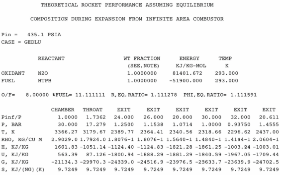
Figure 1. Results for Chemical Combustion from NASA CEA, Software.
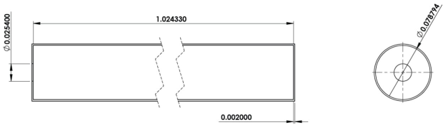
Figure 2. Oxidizer tank dimension.
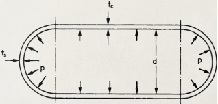
Figure 3. Cross-Section of A Thin Cylinder with Hemispherical Ends.
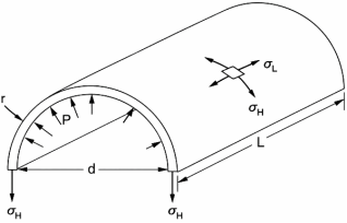
Figure 4. Cross-Section of A Thin Cylinder.
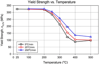
Figure 5. Yield Strength (0.2% Offset) Of 6061-T651 After Prior Exposure at Different Heating Rates.

Information



 Share This Article
 Twitter
 Linked In
 Facebook
 Copy
Copy Download